Cisco Secure Access Help

PDF

Cisco Secure Access Help

Manage Virtual Private Networks

Want to summarize with AI?

Log in

Virtual Private Networks (VPNs) enable users to access your network from a remote location safely and securely.


A remote access VPN allows individual users to connect to a network from a remote location using a computer or other supported device that is connected to the internet. This allows mobile workers to connect from their home networks or a public Wi-Fi network, for example.

Manage the settings and profiles of your remote access VPNs that are registered with Secure Access:

  1. A secure VPN connection requires a VPN profile. A VPN profile is the set of configuration settings that define how a VPN connection will be established, including details like authentication methods, encryption protocols, and server addresses, essentially providing the framework for creating a secure connection to a specific network. For more information, see Manage VPN Profiles.

  2. A fully qualified domain name (FQDN) adds an extra layer of flexibility and precision when you create VPN profiles and access rules, providing enhanced security and simplifying network management. For more information, see FQDNs for Network Connections.

  3. Cisco Secure Access protects the DNS traffic in your organization. Optionally, DDNS (Dynamic DNS) service updates the mappings of domain names to IP addresses to provide accurate IP addresses to DNS clients. For more information, see Manage DNS and DDNS Servers.

  4. Manage your organization's regions and IP address pools that are used to secure the request and response traffic of your remote access VPN profiles. For more information, see Manage Regions and IP Pools.

  5. A remote access VPN machine tunnel ensures connectivity to the corporate network whenever the client system is powered up, not just when a VPN connection is established by the end user. For more information, see Manage Machine Tunnels.

  6. (Optional) Configure a RADIUS group and add servers to the group to apply Authentication, Authorization, and Accounting (AAA) methods to a VPN profile configurations. For more information, see Add a RADIUS Group.


Manage Regions and IP Pools

When setting up a VPN profile, you choose the Secure Access region where your data center is located, which determines where the VPN traffic will be routed within your network.

  • A Secure Access region is a cluster of data centers in a specific geographic area, such as the Northeastern United States or Western Europe. It is best practice to choose a region that is geographically close to users; this reduces latency because data reaches the users more quickly. We strongly recommend adding two regions located as close together as possible to support failover conditions.

  • An IP address pool is a sequential range of IP addresses within a certain network. You can have multiple pool configurations. VPN profiles require IP addressing pools in order to be fully-functional. In addition, control plane traffic such as RADIUS is sourced from the Secure Access IP address pools defined as the System IP pool on the dashboard.

  • Ensure the IP addresses included in System IP pool are allowed to communicate with necessary services hosted on your premises such as Radius servers, DNS servers, CRL/OCSP servers, and other components of Secure Access.

For more information, see Add an IP Pool.

RAVPN IP Pools Best Practice

If the RAVPN service is deployed across multiple regions, each region should be sized to support both normal user load and expected failover scenarios. For example, assume a region normally supports 100 users and requires 100 available client IP addresses to support those users.

For regional failover, if another region becomes unavailable, the surviving region must have enough IP capacity to support its own normal users plus any users failed over from the unavailable region.

For example, if a surviving region normally supports 100 users and also needs to absorb 100 users from another unavailable region, it must support 200 active VPN users and therefore requires 200 available client IP addresses.

The surviving region should also have enough reserved IP capacity to support this 200-user load even if one vEDC in that region becomes unavailable. In this example, the surviving region should have 400 available client IP addresses.

Failover in Regions and IP Pools

For every region selected in this process Secure Access polls different locations within that region to ensure the best VPN connectivity is promoted. To ensure that when failover happens in your region your environment does not affect your connectivity, we recommend adding at least two regions as geographically close as possible. This protects and ensure user connectivity because if data center A is not operating correctly or is experiencing connectivity issues and becomes unavailable, data center B remains active and detects the drop. Data center B automatically loadbalances users from data center A; this action appears as a reset and then users are transferred from data center A to data center B. If you create two data centers in two different regions, the IP addresses may not be viable.

To address failover we strongly recommend adding two regions and also to committing to twice the number of IP addresses in your IP pools to cover all of the users per data center. That means that if there are 150 users per region, you should create a combined IP pool that contains at least 300 IP addresses to accommodate the additional users in a failover scenario.


Add a Region Configuration

Add an IP pool that is used to manage a set of IP addresses for your VPN profile. Optionally, add a RADIUS group for VPN profiles.

Use the following procedure to add new locations with region names, geographic details, and IP address ranges. This creates different regions based on where your users are accessing the internet from. Remember to associate appropriate security policies with each location to manage traffic based on region.

Note that this allows you to create and subsequently add this to an Access Policy rule, making the focus based on an IP address or ip pool. We strongly recommend the folowing practices when crating a region:

  • Create rules based on machine or device identity instead.

  • Add two regions as geographically close as possible to avoid failover.

To add a region configuration, which includes managed IP pools, complete the following steps:

Before you begin

A Full Admin user role is required. For more information, see Manage Accounts.

Procedure

  1. Navigate to Connect > End User Connectivity > Virtual Private Network.

  2. Click Add IP pool to define IP pools that can be used to distribute IP addresses for remote access VPN profiles.


    End User Connectivity page with Add IP Pool option
  3. Define Parameters required to Add a Region Configuration.


    Parameters required to configure regions with unique IP Pools for connecting endpoints
    1. Map the IP pool to an available Region.
    2. Add a meaningful Display name.
    3. Choose a pair of DNS Servers from the drop-down, or click Add to add a new DNS pair.
    4. For the System IP Pool add subnets needed for remote management access to the VPN headend. Supports ranges from /31 to /21. You can add add up to 5 comma-separated ranges. Subnets added here limit the total number of connections added through IP Pools section.
  4. Scroll down and click Add IP pool to define the IP pools needed for the region configuration.

    Note
    To prevent a possible network outage caused by server failure or connectivity issue, we recommend configuring at least two IP pool regions with the secondary region located as close to the primary IP pool region as geographically possible.

    Defining IP pools for region configuration using subnets
    1. Input an IP Pool name that identifies the pool for use with remote access VPN endpoint devices. Each endpoint will be assigned an IP address from a defined IP pools.
    2. Add IPv4 subnets needed for use with remote access VPN endpoints. Each endpoint will be assigned an IP address from the defined IP pool. Supports ranges from /28 to /16. You can add multiple comma-separated ranges.
    3. Add IPv6 subnets (optional). Supports ranges from /124 to /112. You can add multiple comma-separated ranges.
  5. Click Save.


Enable or Disable VPN Regions

Before you enable or disable a region in your organization be aware that this act can drastically alter how your environment operates. If you opt to disable a region be aware of the following consequences:

  • All users connected to the region are immediately disconnected.

  • The disabled region is unreachable to all users.

  • New connections are now routed to other available regions.

You must enable or disable each region individually; you cannot change the status of multiple regions simultaneously by using this tool.

Before you begin

You must have at least one region already configured and deployed in a VPN profile before you can enable or disable a VPN region out of rotation. This action is not available if no regions are configured. For more information see Add a Region Configuration.

Note

While you must have at least one region already configured and associated with a VPN profile, to disable a region, you can disable a region even if it is the only region within you organization.

Procedure

  1. Navigate to Connect > User Connectivity > Virtual Private Network.

  2. Either examine the Regions and IP Pools widget at the top of the window and click Manage. Alternatively, if you are looking for a specific region that is currently enabled or disabled you can click inside the interactive Enabled or Disabled tiles to filter the Regions page by status.

  3. If you did not click the interactive Enabled or Disabled tiles in the previous step, feel free to interact with the tiles in the Regions and IP Pools page to filter the regions displayed.

  4. Locate the region you want to enable or disable from your VPN rotation and click the blue ellipsis at the right end of the row for the region you want to modify.

  5. Select either Enable or Disable.

    Note

    If you are Disabling a region you must confirm the action in the pop-up window by checking the I understand and wish to proceed announcement and then click Disable. It may take several minutes to completely disable the region from your VPN configuration.

What to do next

Depending on the action you took, the region is immediately marked as either enabled or disabled in both the Regions and IP Pools and the End User Connectivity page.

To view details about the connection events for the region or regions that are now disabled, see the Remote Access Log.


Add an IP Pool

An IP address pool is a sequential range of IP addresses within a network, and multiple pools can be configured. VPN profiles require at least one IP pool to function properly. Control plane traffic, such as RADIUS, also uses IP addresses from these pools. IP address pools provided by Secure Access define the parameters used to secure request and response traffic for your VPN connections.

Common uses for IP address pools include:

  • Reserving resources for specific users or groups.

  • Assigning dedicated IP ranges for specific applications.

  • Organizing and securing network traffic based on user roles.

Managing IP address pools helps secure and organize remote access VPN traffic effectively. Use the following procedure to configure IP pools for remote access VPNs in Secure Access.

Note
Note: To ensure optimal performance, follow these IP address allocation guidelines:
  • Allocate at least one system IP per 1,000 anticipated VPN connections.

  • Use a minimum IP block size of /28 (16 addresses).

Before you begin

This procedure requires the following:

  • Full Admin user role. For more information, see Manage Accounts.

  • If you are adding an IPv6 IP pool, ensure your infrastructure and environment is compatible and supports IPv6 connections. Failures occur when there is a mismatch between IP protocols.

  • Unless you have configured your devices to use an alternate CGNAT IP address range, we do not recommend using multicast, RA VPN, CGNAT IP pools or any IP ranges already in use for this procedure. Use non-RFC1918 IP addresses.

  • IP pools cannot include addresses/networks listed in IP Address Restrictions.

  • If you intend to create an IP pool for an ISE integration, confirm any private applications are correctly segregated. Failure to segregate private applications introduces the possibility of the ISE server subnet getting assigned to a ZTA end user. This causes unpredictable behavior when matching traffic against the private application policy.

Procedure

  1. Navigate to Connect > End User Connectivity > Virtual Private Network.

  2. Under Regions and IP Pools, click Manage

    Regions and IP Pools page with option for managing IP pools

    The IP Pools page opens. Each region must have a unique IP pools configured. These IP pools are used to assign IP addresses to endpoint devices connecting via remote access VPN. Proper configuration ensures that VPN clients receive unique IP addresses from the pool associated with their region, preventing IP address conflicts and enabling efficient routing and management of remote access VPN connections.

  3. Take the following actions to manage IP pools.

    • Click Add IP Pool to open a dialog for creating a new IP pool.

    • Click an existing IP pool's region name to view the IP pool detailed information pane.

    • Click the pencil icon to edit an IP pool.

    IP Pools page for managing IP pools for each region
  4. Configure IP pool parameters:

    Parameters required to configure regions with unique IP Pools
    1. Select an available Region.
    2. Enter a Display name.
    3. Select a DNS Server pair from the dropdown, or click + Add to create a new DNS pair.
    4. DDNS Servers updates (optional): Check the box to select an existing DDNS server, or click + Add to create a new DDNS pair.
    5. System IP Pool (optional): Add up to five subnets with IP ranges from /28 to /21 to grant Secure Access permission to obtain IP addresses for administrative connections to customer data centers. Subnets added as system IP pools count against the total number of IP pools available in the next step.
  5. IP Pools: Add the IP pools this region will use. You can add a maximum of 25 IPv4 and 25 IPv6 subnets per IP pool.

    Defining IP pools for region configuration using subnets
    Note
    IP pools cannot include addresses/networks listed in IP Address Restrictions.
    1. Enter an IP pool name.
    2. Add IPV4 subnets for remote access VPN user connections. Each user endpoint will receive an IPv4 address from the IP pool. You may add multiple comma-separated ranges from /28 to /16.
    3. Add IPv6 subnets (optional) for remote access VPN user connections. If configured, each user endpoint will receive an IPv6 address from the IP pool. You may add multiple comma-separated ranges from /124 to /112. The IPv6 user connection count must be greater than or equal to the IPv4 user connection count configured for this IP pool.
  6. RADIUS Groups (optional): Select an existing RADIUS group or click Add RADIUS Group to associate a RADIUS group with this IP pool. For more information, see Add a RADIUS Group.

  7. Click Save & Add IP Pool to finish configuring a new IP pool. Click Save to finish editing an existing IP pool.


Assign an IP Pool

Secure Access provides IP pool configurations to secure the request and response traffic of your VPN profiles. Typically, IP pools would be used to reserve resources for particular users or groups or to make sure that certain ranges are used for particular purposes.

VPN profiles require that you configure and assign at least one IP address pool in order to be fully-functional. IP address pools are managed through the Regions and IP Pools console, which allows you to organize and allocate IP addresses across your regions. You can create pools to represent different organizational units, environments, or regions, making it easier to manage your IP address space.

To assign an IP pool to manage a set of IP addresses for your VPN profile, complete the following steps:

Before you begin

The following are required:

  • Full Admin user role. For more information, see Manage Accounts.
  • At least one IP pool defined for use in VPN profiles.

Procedure

  1. Navigate to Connect > End User Connectivity > Virtual Private Network.

  2. For VPN Profiles, click on a profile to modify or click + VPN Profile to add a new profile.

  3. Under General Settings, click Assign IP Pools and select one IP pool per region from the IP Pool drop-down. VPN profiles must have at least one IP pool assigned in each region for a valid configuration. For more information, see Add an IP Pool.


    General Settings section with option to assign IP pool for a region
  4. Click Save to assign the IP pool to the VPN profile and to clear the alert.


Modify IP Pools

You can modify IP address pools. You can edit a pool's CIDR and other settings through the Regions and IP Pools console.

Procedure

  1. Navigate to Connect > End User Connectivity > Virtual Private Network.

  2. For Regions and IP Pools, click Manage.

  3. Select a region or data center to modify and click the edit icon.

  4. Scroll to IP Pools to edit a pool's CIDR and to add or remove subnets.


    IP Pools section with option to manage subnets or edit pool's CIDR
  5. Optionally, click + Add to create a new IP pool for the region.

  6. Click Save to commit changes or Cancel to exit.


Modify IP Pool Assignment

You can modify which IP pools are mapped to a VPN profile. You can edit a pool's assignment through the VPN Profile console.

Procedure

  1. Navigate to Connect > End User Connectivity > Virtual Private Network.

  2. Choose the profile to modify under VPN Profiles and click the edit icon.

  3. Under General Settings, click Edit assigned IP pools and select another pool from the IP Pool drop-down. VPN profiles must have at least one IP pool assigned in each region for a valid configuration. For more information, see Add an IP Pool.


    General Settings section with option to edit assigned IP pools
  4. Click Save to assign the selected IP pool to the VPN profile.


Manage RADIUS Servers and Groups

Cisco Secure Access integrates with Cisco Identity Services Engine (ISE) to support centralized RADIUS servers that provide Authentication, Authorization, and Accounting (AAA) services for remote users accessing the network.

  • Authentication verifies the identity of the user.

  • Authorization enforces policies that determine which resources and services an authenticated user can access.

  • Accounting tracks user activity for billing, monitoring, and security.

Guidelines for RADIUS protocol and AAA methods:

  • Specify the IP address, port number, and shared key for each RADIUS server. Other settings, such as RADIUS username format and retransmission counts, have default values and can be adjusted based on network requirements.

  • RADIUS server group settings like username format and shared key must match those on the RADIUS server.

  • A maximum of eight servers can be added to a Secure Access RADIUS group.

  • The order of server groups and servers within groups determines the server access order.

  • Authentication Mode: Methods such as MS-CHAPv2 and PAP are supported. The default RADIUS authentication port is 1812 (valid range 1-65535).

  • Authorization Mode: The default RADIUS authorization port is 1812 (valid range 1-65535). Use the Change of Authorization (CoA) port when using the RADIUS group for ISE Policy Enforcement in remote access VPNs. The CoA port is defined in the network device profile and can be modified — ensure consistency between the network device profile and the network device if the CoA port is changed.

  • Accounting Mode: The RADIUS Accounting report tracks user session durations and can help diagnose connectivity issues. The default RADIUS accounting port is 1813 (valid range 1-65535).

  • Environments with an ISE integration and a CNHE network tunnel must have a private access policy; this means that your source should be a Region IP pool and the destination should be an ISE Server IP address.

Note
RADIUS servers cannot use addresses/networks listed in IP Address
Restrictions

Add a RADIUS Group

This section describes how to configure a RADIUS group and add servers to the group. This RADIUS group can be applied to the Authentication, Authorization, and Accounting (AAA) methods of a VPN profile configuration and mapped to other VPN profiles.

Before you begin

A Full Admin user role is required. For more information, see Manage Accounts.

Procedure

  1. Navigate to Connect > End User Connectivity > Virtual Private Network.

  2. Under VPN Profiles, click Add.

  3. Complete General settings of the VPN Profile and click Next.

  4. Under Authentication, Authorization, and Accounting, expand Map authentication groups to regions, then click + Group.

    Adding RADIUS Group
  5. Associate up to one RADIUS group per AAA method to control access to VPN profiles. Add up to eight RADIUS servers to each group.

    1. Enter a Group Name.
    2. Choose and configure one or more AAA methods.
      • Each method requires a port number between 1 to 65535 for RADIUS authentication.
      • Authentication:
        • The default port number is 1812.
        • The Authentication and Authorization methods must have the same port number when used together.
        • Check Microsoft CHAPv2 to use Microsoft Challenge Handshake Authentication Protocol Version 2 as the authentication method.
      • Authorization:
        • The default port number is 1812.
        • The Authentication and Authorization methods must have the same port number when used together.
        • Check Authorization mode only to require no common password.
        • Check Change of authorization (CoA) mode to register the RADIUS server group for CoA notification. If you enable CoA, the listening port for RADIUS CoA requests uses the default of 1700. Use the CoA port when using the RADIUS group for ISE Policy Enforcement in remote access VPNs. The CoA port is defined in the network device profile and can be modified — ensure consistency between the network device profile and the network device if the CoA port is changed.
      • Accounting:
        • The default port number is 1813.
        • Under Accounting mode select Single to send accounting data to one server, or Simultaneous to send accounting data to all servers in the group.
        • When Cisco ISE is integrated with a Cisco ASA, set the ASA Accounting mode to Single.
        • Check Interim accounting update to enable the periodic generation of RADIUS interim-accounting-update messages.
    3. Configure Settings.
      • Max failed attempts: Configure the maximum number of failed AAA transactions (from 1 to 5; default is 3) before authentication will try the next RADIUS server in the group.
      • Reactivation mode:
        • Select Depletion to reactivate failed servers only after all of the servers in the group are inactive. Configure the Dead time (0 to 1440 minutes; default is 10 minutes) that must elapse between the time when the last RADIUS server in the group is disabled and the time when all servers will be reenabled. Authentication will be attempted locally until dead time elapses. Note: Dead time applies only when fallback to the local database is configured.
        • Select Timed to reactivate failed servers after 30 seconds of down time.
        • Servers timeout: The number of seconds to wait for a response from a RADIUS server. Default is 10 seconds.
    4. RADIUS Servers: Add up to eight existing RADIUS servers to the group, or click + Add to configure a new RADIUS server.
      Add RADIUS servers to RADIUS group or configure new RADIUS server
      Note
      RADIUS servers cannot use addresses/networks listed in IP Address
 Restrictions.
    5. Click Save.

Test a RADIUS Server Connection

Regions are used to map RADIUS server or groups for authentication, authorization, and accounting (AAA) purposes. When configuring a RADIUS server in Secure Access, you must select the regions and associate them with the appropriate RADIUS groups to ensure the servers are correctly assigned per each region. We recommend testing server connectivity prior to deploying as connectivity to regions immediately affects the mapping to all three AAA functions. Note that you must test each connection individually, but you can test one connection against multiple regions simultaneously.

Before you begin

Before you can test the connection with the configured RADIUS server, you must have the following established:

  • You must have an AAA sever already configured.

  • The CNHE tunnel must be established and connected. Check your configuration and tunnel status in the Network Tunnel Groups tab of the Connect > Network Connections page.

  • The user you intend to test the connection with should be included the Users tab of the Connect > Users, Groups, and Endpoint Devices page. If there are no users then you cannot test in that region.

  • You must have at least one group assigned to the region.

  • You must have at least one VPN profile deployed within the region you intend to test.

Procedure

  1. Log into your Cisco Cloud Control organization and navigate to Security > Resources > Configuration > AAA Servers .

  2. Click the RADUS Servers tab.

  3. Click Test Connection.

  4. Use the drop-down menu and select the RADIUS server want to test.

  5. In the Server Info & Credentials window confirm the following:

    • Server IP address.

    • Authentication type.

    • Groups associated.

    • VPN Profiles.

  6. In the Test Account Credentials enter your organization username and password.

  7. Expand the Regions to test window and expand the drop-down menu to select at least one region to test against. While the group that is already associated with the region is automatically selected by the system and is listed at the top of the drop-down menu, you can select any region to test with.

  8. Click Run Test. A system-issued test executes and runs for 30 seconds per test before timing out. Test results are displayed within this window. Click View details to review unsuccessful connection test details to troubleshoot the connection.

What to do next

If you experience issues with connectivity, contact Cisco Support.


Manage VPN Profiles

A Remote Access Virtual Private Network (VPN) enables individual users to securely connect to a private network from any remote location using a computer or other supported device with Internet access. This functionality is particularly valuable for mobile workers who need to connect from home networks or public Wi-Fi environments.

You can enable persistent remote access in your VPN profiles with the Always On option.

Key features of Always On:

  • Automatic connection: AnyConnect automatically connects to the VPN when the user logs in to their computer.

  • Policy enforcement: Protects the computer from security threats by preventing access to Internet resources when not connected to a trusted network.

Important considerations when using Always On:

  • Digital certificates: We recommend purchasing a digital certificate from a certificate authority and enrolling it on secure gateways.

  • User login requirement: If Always On is enabled but the user does not log on, the AnyConnect VPN connection will not be established.

  • Windows Updates: We strongly recommend ensuring both your Windows operating system is up to date with sustem-provided updates and your Windows Defender account is not out of date. Insufficient versioning and noncompliance causes policy failure.

The Allow VPN Disconnect feature accompanies Always On functionality, providing users with the flexibility to disconnect from their current VPN session when needed. Common use cases of Allow VPN Disconnect:

  • Selecting an alternative secure gateway due to performance issues.

  • Resolving reconnection issues following a VPN session interruption.

  • Troubleshooting connectivity problems.

For additional configuration details, refer to the following documentation:


Add VPN Profiles Step 1 – General Settings

A virtual private network (VPN) connection establishes a secure tunnel between endpoint devices over a public network such as the Internet. This section describes how to create VPN profiles to allow for configuration of remote user connections through a VPN.

The first step is to name and configure the general settings of the VPN profile.

Before you begin

This procedure requires the Full Admin role in Secure Access. See Manage Accounts for more information.

Procedure

  1. Navigate to Connect > End User Connectivity > Virtual Private Network.

  2. Under VPN Profiles, click + VPN Profile.

    VPN profile section with option to add VPN profile
  3. Enter basic profile information.

    Field Description Required
    VPN profile name Enter a name to identify this profile. Yes
    Display name Enter a customizable label that end-users will see in Cisco Secure Client when selecting a profile. No
    Default Domain Specify the default domain for this profile. Yes
  4. Configure DNS settings.

    1. By default, DNS Servers is set to Region specified, meaning the VPN profile uses the DNS servers designated for each region.
      Option Description Required
      View DNS servers Click to see the list of DNS servers mapped to regions No
      Custom specified Select to use a custom DNS pair instead of the regional default. Click Map DNS servers to open the configurable view and select from available DNS servers. For detailed instructions, see Map DNS Servers to Regions No
    2. By default, DDNS Servers is set to Region specified, meaning the VPN profile uses the DDNS servers designated for each region.
      Option Description Required
      DDNS Servers updates Check to enable dynamic updates to domain name-to-IP address mappings when a remote user's network IP address changes. For more information, see Map DDNS Servers to Regions No
  5. Click Assign IP pools and select one IP pool per region from the IP Pools drop-down.

    VPN profiles must have at least one IP pool assigned in each region for a valid configuration. For more information, see Add an IP Pool.
  6. Under IP version mode, select one or both options:

    • IPv4

    • IPv6

  7. Under Protocol, select at least one protocol:

    • TLS/DTLS

    • IKEv2

    Note
    If both protocols are selected, choose the primary protocol from the Primary drop-down menu.
  8. From the Connect time posture drop-down, select a posture profile if required. For more information, see Add a VPN Connection Posture Profile.

  9. Click Next to proceed to Add VPN Profiles Step 2 - Authentication, Authorization, and Accounting.


Add VPN Profiles Step 2 – Authentication, Authorization, and Accounting

Authentication is how a remote user is identified before being allowed to access networks and network resources over VPN. Authentication requires valid user credentials, a certificate, or both. Use authentication alone, or with authorization and accounting.

Choose one of the following authentication methods from the Protocols drop-down, then follow the procedure for that method.


Add VPN Profiles Step 2 - SAML

When you choose SAML for remote access VPN authentication, each user is authenticated using the SAML single sign-on server. SAML authentication for remote access VPN supports SAML, SAML + Single CA certificate, and SAML + Multiple CA Certificates.


Authentication, Authorization, and Accounting section with SAML Configuration option for user authentication
In Secure Access, you can add the same SAML identity provider (IdP) in multiple VPN profiles. Secure Access does not support the configuration of different settings for the same SAML IdP in multiple VPN profiles so you must configure the same SAML IdP metadata in all of the VPN profiles in order to use the IdP for more than one profile, as well as enable the same metadata, certificate, and re-authentication settings for the SAML IdP. Without this information present in all the affected profiles, the user credentials fail for the IdP serivce.

Procedure

  1. Select SAML from the Protocols drop-down.

  2. Authenticate with CA certificates: Select to use CA certificates to authenticate this VPN profile.


    Authentication using CA certificates
    Note
    If you select SAML attribute name with the intention of selecting the posture profile with the VPN profile, then the authentication type of said VPN profile should be SAML+Cert or SAML+Multicert based on how many certificates you want to select for posture endpoint. The SAML attributes must be present and match the certificate attributes.
  3. Select options under SAML Configuration:

    • External browser authentication — Select this option to have Secure Client use a local browser for authentication. When selected, Secure Client can support other SAML-based web authentication options, such as Single Sign On, biometric authentication, or other enhanced methods that are unavailable with an embedded browser.
    • Forced re-authentication — Select this option to force a re-authentication whenever a VPN connection is initiated. Forced re-authentication is related to the Session Timeout setting. For more information see Cisco Secure Client Configuration.
  4. Choose a configuration method.

    1. Click SAML Metadata XML Configuration to configure SAML authentication with your service provider XML file.
      1. Click Download service provider XML file. This XML file contains metadata required to configure your IdP. Upload this file to your IdP.
      2. Generate IdP Security Metadata XML file — From your IdP, create and download an IdP Security Metadata XML file.
      3. Upload IdP security metadata XML file to the SAML metadata XML configuration in Secure Access.
    2. Click Manual Configuration to configure SAML authentication manually with information from your Service Provider (SP) and Identity Provider (IdP).
      1. Download the SP Certificate.
      2. Obtain the following from the SAML IdP:
      • Identity Provider Entity ID URL.
      • Sign-in URL.
      • Sign-out URL.
      • IdP Certificate.
      • Request Signature.

What to do next

For more information about Secure Access and SAML for VPNs with a configured VPN profile, see Manage SAML Certificates for Identity Providers.


Add VPN Profiles Step 2 - RADIUS

Use this option to authenticate users on a RADIUS server.

Note
Cisco strongly discourages the use of RADIUS (RADIUS username/password only) as a single form of authentication. If the RADIUS server does not provide multi-factor authentication (MFA), then you must enable a second factor of authentication in Secure Access for VPN authentication. You can configure certificates in Secure Access as the second form of authentication.

When you choose RADIUS, each user is authenticated using RADIUS group servers. RADIUS authentication for remote access VPNs supports RADIUS, RADIUS+ Single CA certificate, and RADIUS+ Multiple CA Certificates.


Authenticate using RADIUS group servers

Add VPN Profiles Step 2 - Certificates

Use this option to authenticate users with trusted certificate authorities (CAs).

When you choose Certificate, each user is authenticated with a client certificate. The client certificate must be configured on VPN client endpoints. By default, the user name is derived from the client certificate fields CN and OU. If the user name is specified in other fields in the client certificate, use the Primary field to authenticate and Secondary field to authenticate field to map appropriate fields.

Select Multiple Certificates authentication to authenticate the VPN client using the machine and user certificates.

If have enabled Multiple Certificates authentication, you can select one of the following certificates to map the username and authenticate the VPN user:

  • First Cert—Select this option to map the username from the machine certificate sent from the VPN client.

  • Second Cert—Select this option to map the username from the user certificate sent from the client.

Note
If you do not enable multiple certificate authentication, the user certificate (second certificate) is used for authentication by default.

Add VPN Profiles Step 3 – Traffic Steering (Split Tunnel)


Step 3a – Traffic Steering (Split Tunnel)

For Traffic Steering (Split Tunnel), you can configure a VPN profile to maintain a full tunnel connection to Secure Access, or configure the profile to use a split tunnel connection to direct traffic through the VPN only if necessary.

Procedure

  1. Tunnel Mode: Choose Connect to Secure Access or Bypass Secure Access for the default traffic steering mode.

    • Connect to Secure Access directs all traffic through the tunnel. Note that DNS names matching the configured DNS Names are routed over the local physical interface for the resolution. Any that do not match the configured DNS Names are routed via the encrypted Secure Client connection for resolution.


      Configuration of Connect to Secure Access tunnel mode as default traffic steering mode
    • Bypass Secure Access directs all traffic outside the tunnel.


      Configuration of Bypass Secure Access tunnel mode as default traffic steering mode
  2. Add Exceptions for specific sources and destinations to steer traffic inside or outside the tunnel, depending on the Tunnel Mode.

    1. Click + Add.

    2. Enter the name of a Network Object or a Network Object Group in the search bar and then select the same on the Select sources tab.


      Add Destinations section with option to search for sources for traffic steering

      Or

      On the Add a source tab, enter comma-separated IPs, domains, and network spaces.


      Add Destinations section with option to add sources for traffic steering
    3. Click Save.

  3. Local LAN Access: If Cisco Secure Client will be configured in the next step to allow the user complete access to the local LAN connected to the remote computer during the VPN session to Secure Access, add a traffic steering exception configured for IP range 0.0.0.0/32. For information about configuring Local LAN Access, see Client Settings (General) under Step 4 – Cisco Secure Client Configuration.

    Add traffic steering exception configured for IP range
  4. Click Next to configure the Cisco Secure Client.


Step 3b – Proxy and DNS Steering Settings

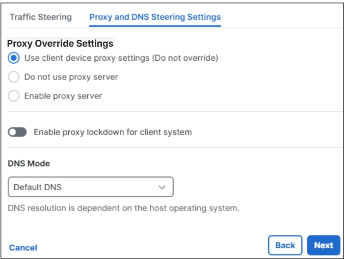
Use Proxy and DNS Steering Settings to manage how VPN clients handle proxy routing and DNS resolution. You can configure the VPN profile to bypass the proxy server for specific destinations or ports, or enforce the use of an alternative proxy server.

Procedure

  1. For Proxy Settings, choose one of the following options:

    • Use client device proxy settings (Do not override): Allow the user to configure a browser proxy for HTTP traffic and use the proxy if it is configured.

    • Do not use proxy server: Prevent the use of browser-configured proxies. No browser connections will be routed through the proxy.

    • Enable proxy server: Configure and enforce the use of a proxy server for client devices.


    Configuration of Proxy and DNS Steering Settings
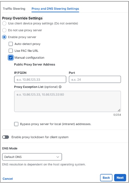
  2. When Enable proxy server is chosen, the following proxy server settings options are displayed. Choose the required settings:

    • Auto-detect proxy: Check this box to specify the URL where the Proxy Auto-Configuration (PAC) file is located.

    • Use PAC file URL: Check this box to provide the PAC file URL.

    • Manual configuration: Check this box to manually define a proxy server to be used by all client devices for HTTP traffic. Then, configure the following:

      • Public Proxy Server IP: Enter the IP address or hostname of the public proxy server and specify the port.

        Note

        The combined length of the hostname and port cannot exceed 100 characters.

      • Proxy Exemption List (optional): Add host/port combinations that should bypass the proxy. Enter the public proxy server address before adding exceptions.

        Note

        You must enter the public proxy server address before adding exceptions.

      Note

      To bypass the proxy for local addresses, check the Bypass Proxy Server for Local (Intranet) Addresses checkbox.


      Configuration of Proxy and DNS Steering Settings with Enable proxy server option
  3. (Optional) Use the Enable Proxy Lockdown for Client System toggle button to activate proxy lockdown for the client system.

  4. For DNS Mode, choose one of the following:

    • Default DNS: This is the system-provided DNS option. All traffic is resolved with the default DNS server configured during the connector deployment stage.

    • Tunnel all DNS: Route all DNS traffic over the encrypted VPN connection.

    • Split DNS : Route DNS names are matched over the local physical interface. Names that do not match are handled through the VPN connection.

  5. Click Next to configure the Cisco Secure Client.


Add VPN Profiles Step 4 – Cisco Secure Client Configuration

You can modify a subset of Cisco Secure Client settings based on the needs of a particular VPN profile.

Procedure

  1. Click the Session Settings tab to modify session-specific settings:


    Update Session Settings
    • Banner Message—Configure a banner message for the user to accept after Secure Client authentication.

    • Session Timeout—Configure a time window after which the Secure Client session will end. The default is 4 hours.

    • Session Timeout Alert—Configure the number of minutes before the session timeout to alert the user. The default is 30 minutes.

    • Idle Timeout — Configure a time window for an idle Secure Client session, after which the session will end.

      Note

      This value affects the Disconnected Timeout configuration in your Cisco AnyConnect settings; which determines when AnyConnect/Secure Client ceases reconnect attempts since the session to the ASA has been interrupted.

    • Idle Timeout Alert—Configure the number of minutes before the idle session timeout to alert the user. The default is 1 minute.

    • Maximum Transmission Unit (MTU)—Configure the largest packet size that can be transmitted through the VPN tunnel before fragmentation. Accepts a value between 576 and 1390.

    • Smart card removal—Check Maintain VPN session to continue the VPN connection in the event of a smart card removal. Otherwise the VPN connection is terminated when a smart card is removed.

  2. Click the Client Settings tab then click Edit to modify client-specific sessions. See The Cisco Secure Client Profile Editor for complete information about Cisco Secure Client settings.

    1. Modify Session Settings as needed.


      Update Session Settings
    2. Modify Client Settings (General) as needed.


      Update General Client Settings
      Note
      Local LAN Access allows the user complete access to the local LAN connected to the remote computer during the VPN session to Secure Access. If enabled, Local LAN Access requires a traffic steering exception configured for IP range 0.0.0.0/32. For more information, see Step 3a – Traffic Steering (Split Tunnel).
    3. Configure a time window for an idle Secure Client session, after which the session will end. Note: This value affects the Disconnected Timeout configuration in your Cisco AnyConnect settings; which determines when AnyConnect/Secure Client ceases reconnect attempts since the session to the ASA has been interrupted. Modify Client Settings (Administrator) as needed.


      Update Client Administration Settings
      • Windows Logon Enforcement—Allows a VPN session to be established from a Remote Desktop Protocol (RDP) session.

      • Windows VPN Establishment— Determines how Cisco Secure Client behaves when a user remotely logs on to the client PC and establishes a VPN connection.

      • Linux Logon Enforcement— Allows a VPN session to be established from an SSH session.

      • Linux VPN Establishment— Determines how Cisco Secure Client behaves when a user logs on to the client PC using SSH and establishes a VPN connection.

      • IP Protocol Supported—Cisco Secure Client decides which IP version to use, IPv4 or IPv6, when connecting to Secure Firewall ASA.

      • Proxy Settings—Specifies a policy in the Cisco Secure Client profile to control access to a proxy server. Use this when a proxy configuration prevents a tunnel from being established outside the corporate network.

      • Authentication Timeout Values—Defines the number of seconds the client waits for an authentication response after sending user credentials. Enter a number from 10 to 120.

    Note
    To enable and configure the Always-On operation, which prevents access to Internet resources without a server certificate when the computer is not on a trusted network (unless a VPN session is active), check the Automatic VPN Policy option, then scroll down and check the Always on VPN option, optionally.

    Automatic VPN Policy (Windows and macOS only)—Enables Trusted Network Detection allowing Cisco Secure Client to automatically manage when to start or stop a VPN connection according to the Trusted Network Policy and Untrusted Network Policy. If disabled, VPN connections can only be started and stopped manually. Setting an Automatic VPN Policy does not prevent users from manually controlling a VPN connection.

    Accessible hosts with VPN disconnected: Enables endpoints to access the configured hosts while VPN is disconnected during Always On. Values are a comma-separated list of hosts which can be specified IP addresses, IP address ranges (CIDR format), or FQDNs. A maximum of 500 hosts are allowed, and wildcards are not supported.
  3. Click Save.

  4. Modify any Client Certificate Settings as needed.


    Update Client Certificate Settings
  5. Click Save to complete the VPN Profile.


    Save Cisco Secure Client configuration

Import ASA Device Configuration Files for Remote Access VPN

The remote access VPN Migration tool facilitates the transfer of remote access VPN configurations from your current firewall solution to the cloud-based Cisco Secure Access VPNaaS environment that provides enhanced security, centralized management, and scaling capabilities. As part of the migration process, the configuration file from your device is seamlessly translated into a Secure Access policy to recreate the remote access VPN configuration and minimize downtime.

Check the following required prerequisites and configurations before you import any ASA configuration files with this tool.

Prerequisites

Ensure the following prerequisites are established before you import a configuration file from your ASA device:

  • Full admin access to the Secure Access dashboard.

  • ASA Device with Remote Access VPN Configuration(s).

Supported Functionality

The following certificate authentication methods are supported with this import tool:

  • SAML + Cert Authentication

  • SAML-only Authentication

  • RADIUS + Cert Authentication

  • Radius-only Authentication

  • Certificate-only Authentication

The following functionality is supported with this migration tool:

  • Group policy

  • Network Objects (split and full tunneling)

    Warning

    Nested network objects within a network object group may cause an error during the procedure.

  • ACL redirect

  • Custom attributes:

    • Per App VPN

    • Bypass Virtual Subnets

    • Split Exclude Failover

  • SSL/IPsec settings

  • IPsec/SSL VPN groups

  • DNS server assignment

  • Radius Servers with dedicated management platforms

  • Radius Server Assignments

  • CA Certificates

  • Full support for VPN profile configurations

Note
The import function described here does not include upgrades for your Cisco Secure Client. As of the publication of this note you must upgrade the Client through the ASDM dashboard. See Migrate AnyConnect Host Scan Migration 4.3.x to 4.6.x and Later for more information.

Import an ASA Configuration to Secure Access Remote Access VPN Profile

If you happen to log out or navigate away from the screen at any point after starting the import process, your progress is saved.

Use this procedure to import the ASA configuration file from a standalone ASA device to Secure Access. Complete the following procedure to migrate your existing remote access VPN tunnels from the ASA firewall to Secure Access and set up the settings in the resulting VPN profile.

Note
This procedure is for generating a VPN profile in Secure Access from an existing ASA remote access VPN configuration, not for creating a new profile independently.

Procedure

  1. In Secure Access, navigate to Connect > End User Connectivity > Virtual Private Network.

  2. In the VPN Profiles section of the window select Import from ASA.

  3. In the Import from ASA page, examine the Upload ASA Configuration and XML Files section of the window. Download the configuration file with either the ASDM dashboard or CLI and then drag one (or more) configuration files from your local device and drop it into the box or click inside the box and navigate to it when prompted.

    Note
    Note that the files must be a maximum of 10 MB. The VPN XML profile can be obtained from the VPN endpoint in the Secure Client folder, with the exact location depending on your operating system. Refer to the "Locations to Predeploy the Cisco Secure Client Profiles" chapter of the Cisco Secure Client Administrator Guide, Release 5.1 for detailed folder locations.
  4. The status of the upload is visible in the upper right corner of the Upload ASA Configuration and XML Files window and the status of the file upload.

    Note
    If a file fails to upload, confirm the file size is smaller than 10 MB and is a supported filetype. At this time only .cfg and .xml files are supported.
  5. Click Next.

  6. In the Review Imported Objects window, review and modify the list of servers and server groups (DNS servers, Radius Groups, Client Authentication certificates, and network objects and object groups) that get imported as part of the import. These items must be error-free to continue. Use the edit or delete icons for the corresponding entry that needs to be corrected and resolve any issues. Note that some objects may have errors due to incompatible or duplicate naming conventions.

    Warning
    Nested network objects within a network object group may cause an error. If you experience this issue, delete the affected network object groups from the list of objects to review and export your device configuration as a CSV file. Upload this file in the Resources > Network and Service Objects page and continue with this procedure.
  7. Click Next

  8. In the Prerequisites window, click +Add Region to create a new region and map the DNS Servers and radius group that was imported as part of the prevous step. If desired, expand the DNS Servers drop-down menu to opt to select "Imported from ASA" as your DNS selection.

  9. Save the region and IP pool and click Next.

  10. In the Edit and Import Configuration Files window, review the VPN profiles detected in the configuration files you uploaded.

    Note
    You cannot proceed if the imported VPN profiles have an incomplete status. Click the edit icon to edit the VPN profile configuration where prompted. See General Settings, Authentiation Authorization and Accounting, and Traffic Steering (Split Tunnel) for more information.
  11. Click Save. You are redirected to the Connect > End User Connectivity > Virtual Private Network page.


Download an ASA Configuration File with ASDM

We strongly recommend this method of downloading an ASA configuration file. If you don't have ASDM installed already, see Cisco ASA General Operations ASDM Configuration Guide and install it prior to the steps in the proocedure below.

If you must use CLI to upload the configuration file, see Download an ASA Configuration File with CLI.

Procedure

  1. Open the ASDM dashboard and enter the IP or FQDN of the ASA, and a username and password for the admin account.

  2. In the ASDM dashboard, navigate to Tools > Backup Configuration and uncheck all options but Running Configuration.

  3. Click Browse Local and select where to save this file locally. Click Select File and then Backup. The file is saved as running-config.cfg.

What to do next

Download the ASA XML file before you continue with the remainder of the procedure.


Download an ASA Configuration File with CLI

The preferred method of downloading an ASA configuration file is with the ASDM dashboard.

For users who opt for the CLI method of downloading,follow the procedure below. See Cisco Secure Firewall ASA Series General Operations CLI Configuration Guide, 9.19 for more information about CLI commands in ASA devices.

Note
Be sure to identify the correct profile in the procedure below; the VPN XML profiles are specified as AnyConnect client profiles and could be mistaken as non-XML files.

Procedure

  1. Open an SSH Client like Putty and then enter the IP/FQDN of the ASA and the username/ password of an account with admin privileges.

  2. Execute the enable command and enter the admin password if prompted.

  3. Enter the show running-config command to display the actively running configuration.

  4. Manually copy the entire output and save it locally.

What to do next

Download the ASA XML file before you continue with the remainder of the procedure.


Download the ASA XML File

The VPN XML profile can be obtained from the VPN endpoint in the Secure Client folder, with the exact location depending on your operating system. Refer to the "Locations to Predeploy the Cisco Secure Client Profiles" chapter of the Cisco Secure Client Administrator Guide, Release 5.1 for detailed folder locations.

Choose one of the following procedures to download the XML file from your ASA device. Do not do both procedures.

Download the ASA XML File with ASDM

  1. Log into the ASDM dashboard.

  2. Navigate to Configuration > Remote Access > Network (Client) Access > Secure Client Profile. to identify the correct locations and filenames.

  3. Check the Profile Location column and ensure the Profile Usage is set to AnyConnect VPN Profile.

  4. Navigate to Tools > File Management.

  5. At the top, select File Transfer, then choose Between Local Device and Flash.

  6. On the left, select the directory where you want to export the file.

  7. On the right, select the appropriate VPN XML profile file as identified above.

  8. Click the left arrow button in the center to transfer the file.

  9. Complete the upload wizard with step 4.

Download the ASA XML File with CLI

  1. Open an SSH Client like Putty and then enter the IP/FQDN of the ASA and the username/ password of an account with admin privileges.

  2. Run the command show running-config webvpn.

  3. Locate the Anyconnect profiles subcommand; note that the command needs to include both the location and the filename . For example, if you see anyconnect profiles VPN_Profile disk0:/secure_client_profile.xml then disk0:/secure_client_profile.xml is the file you need., where "disk0:/" is the location and "secure_client_profile.xml" is the filename.

  4. Display the file with the more [profile location]:/[name].xml command.

  5. Copy the output and save it as a .xml file. Do not include command prompt when you copy.

  6. Complete the upload wizard with step 4.


Manage VPN Settings

Administrators can prevent end users from manually entering any VPN headend on the Cisco Secure Client by unchecking the Allow Manual Host Entry check box. This ensures that end users can only select the VPN headend explicitly defined in the VPN profile configuration, thereby helping to prevent any risk of data exfiltration. Note that enabling this option also allows your remote access VPN configuration to process traffic that would otherwise be dropped due to the DF Bit setting on your system. For example, if a device's MTU is higher than the VPN headend's effective MTU, meaning the device is configured to process a maximum byte-size a data packet can be and the VPN has a smaller MTU size, packets that do not match the VPN headend size are dropped despite the device's MTU allowance. With this option, packets are fragmented and processed within the range of the VPN.


Manage Manual Host Entries for VPN Profiles

This setting applies to all VPN profiles crated for the current organization. To restrict or allow end users from manually creating any unsolicited VPN profiles, perform the following steps:

Procedure

  1. Navigate to Connect > End User Connectivity > Virtual Private Network.

  2. In the VPN Profiles section, click Settings and then select VPN Settings.

  3. View the Allow manual host entries option. To restrict manual host entries from end users, uncheck this option. To allow manual host entries from end users and allowing fragmentation for packets that are larger than the VPN headend value, leave this option checked and proceed to the next step.


    Configuration of Advanced Settings for VPN profile
  4. If you have "Manual Host Entries" enabled, check the appropriate Packet Fragmentation protocols this option is applied to once deployed. Allowing fragmentation at this level breaks down packets that are too large for the VPN headend's configured MTU for analysis instead of dropping them.

  5. Click Save.


Manage Machine Tunnels

A Secure Access VPN machine tunnel ensures connectivity to the corporate network whenever the client system is powered up, not just when a VPN connection is established by the end user. You can perform patch management on out-of-the-office endpoints, especially devices that are infrequently connected by the user, via VPN, to the office network. Endpoint OS login scripts that require corporate network connectivity also benefit from this feature. For this tunnel to be created without user interaction, certificate-based authentication is used.

About the VPN Machine Tunnel

The Secure Access machine tunnel allows administrators to have the Cisco Secure Client connected without user intervention prior to when the user logs in. Secure Access machine tunnel is triggered when the endpoint is off-premises and disconnected from a user-initiated VPN. The Secure Access VPN machine tunnel is transparent to the end user and disconnects automatically when the user initiates VPN.

The Secure Client VPN agent service is automatically started upon system boot-up. The Secure Client VPN agent uses the VPN profile to detect that the machine tunnel feature is enabled. If the machine tunnel feature is enabled, the agent launches the management client application to initiate a machine tunnel connection. The management client application uses the host entry from the VPN profile to initiate the connection. Then the VPN tunnel is established as usual, with one exception: no software update is performed during a machine tunnel connection since the machine tunnel is meant to be transparent to the user.

The user initiates a VPN tunnel via the Secure Client, which triggers the machine tunnel termination. Upon machine tunnel termination, the user tunnel establishment continues as usual.

The user disconnects the VPN tunnel, which triggers the automatic re-establishment of the machine tunnel.

For information about viewing connection events filtered by machine tunnel, see View the Remote Access Log Report.

Limitations

  • User interaction is not supported.

  • Certificate-based authentication through Machine Certificate Store (Windows) is only supported.

  • Strict Server Certificate checking is enforced.

  • A private proxy is not supported.

  • A public proxy is not supported (ProxyNative value is supported on platforms where Native Proxy settings are not retrieved from the browser).

  • Secure Client Customization Scripts are not supported.


Add a Machine Tunnel and Configure General Settings

This section describes how to configure Secure Access as the VPN gateway and accept connections from the Secure Client through the VPN machine tunnel.

Before you begin

  • Full Admin role in Secure Access. For more information, see Manage Accounts.

Procedure

  1. Navigate to Connect > End User Connectivity > Virtual Private Network.

  2. Navigate to VPN Profiles and configure the general settings for the machine tunnel.

    1. Click +VPN profile, navigate to Profile Settings, and then click +Add Machine Tunnel.

      Profile Settings section with option for adding machine tunnel
    2. Click Settings, and then choose Manage Machine Tunnel from the drop-down.

      Configuration of general settings for machine tunnel
  3. Enter the Default domain.

  4. The DNS Server mapped through the Manage Regions and IP Pools page is set as the default server. You can accept the default DNS server, choose another DNS server from the drop-down, or click + Add to add a new DNS server pair. Selecting another DNS server or adding a new DNS server overwrites this default server.

  5. Select one IP pool per region from the IP Pools drop-down. VPN profiles must have at least one IP pool assigned in each region for a valid configuration.

  6. Select the Tunnel Protocol that this machine tunnel will use.

    Note
    Select at least one protocol.
    • TLS/DTLS
    • IPSec (IKEv2)
  7. Optionally, check Include protocol to enforce client bypass protocol.


    General Settings section with option for enforcing client bypass protocol

Configure Authentication for Machine Certificate

The machine tunnel is transparent to the end user and disconnects automatically when the user initiates a VPN session. For this tunnel to be created without user interaction, certificate-based authentication is used.

Set up the authentication for the machine certificate.

Procedure

  1. Choose CA certificates from the list or click Upload CA certificates.

    These certificates can be used by the machine tunnel as a machine certificate to authenticate devices.

    Upload your organization's signed CA root certificate. For more information, see VPN Certificates for User and Device Authentication.


    Authentication for Machine Certificate section displaying options to view list of CA certificates or upload new CA certificate for device authentication
  2. Select the certificate-based authentication fields.

    1. For Primary field to authenticate, choose the certificate field that contains the device name (computer name).
      Secure Access uses the device name as the machine tunnel identifier. The format of the computer name must match the format of the chosen device identifier. For more information, see Authenticate Device Identity with Active Directory.
    2. (Optional) For Secondary field to authenticate, choose a secondary attribute to authenticate to Active Directory endpoint devices.
      You cannot choose the same value for the primary and secondary authentication fields.
  3. Click Next.


Configure Traffic Steering (Split Tunnel)

For Traffic Steering (Split Tunnel), you can configure a machine tunnel to maintain a full tunnel connection to Secure Access, or configure it to use a split tunnel connection to direct traffic through the VPN only if necessary.

Procedure

  1. For Tunnel Mode, choose either:

    • Connect to Secure Access to direct all traffic through the tunnel; or,


      Tunnel Mode section showing Connect to Secure Access tunnel mode configuration to steer traffic through the tunnel
    • Bypass Secure Access to direct all traffic outside the tunnel.


      Tunnel Mode section showing Bypass Secure Access tunnel mode configuration to steer traffic outside the tunnel
  2. Depending on your selection, you can Add Exceptions to steer traffic inside or outside the tunnel.

    1. Click +Add.
    2. In the search bar, enter the name of a Network Object or a Network Object Group in the search bar, click Select sources and then select the same on the Select sources tab.
    3. Click the Add a source, and then enter comma-separated IPs, domains, and network spaces.
    4. Click Save.
  3. For DNS Mode, you can accept the default mode or, depending on your selection, choose to Tunnel all DNS traffic or Split DNS traffic.

    When Split DNS is chosen, DNS names matching the configured DNS Names will be routed over the encrypted Secure Client connection for resolution. Any that do not match the configured DNS Names are routed via the local physical interface for the resolution.

    Note

    At this time, Split DNS is only available for Bypass Secure Access tunnel mode.

  4. Click Next, and then configure the Cisco Secure Client.


Define the Cisco Secure Client Configuration

You can modify a subset of Cisco Secure Client settings based on the needs of a particular VPN machine tunnel.

Procedure

  1. Review the options presented on the Cisco Secure Client Configuration tab.


    Review and update Cisco Secure Client Configuration
  2. Configure the options that are specific to your machine tunnel.

    • Local LAN Access—Allows the user complete access to the local LAN connected to the remote computer during the VPN session to Secure Access.

      Note
      Enabling local LAN access can potentially create a security weakness from the public network through the user computer into the corporate network.
    • Disable Captive Portal Detection—When Cisco Secure Client receives a certificate with a common name that does not match the Secure Access name, a captive portal is detected. This behavior prompts the user to authenticate. Some users using self signed certificates may want to enable connection to corporate resources behind an HTTP captive portal and should thus mark the Disable Captive Portal Detection checkbox. The administrator can also determine if they want the option to be user configurable and mark the checkbox accordingly. If user configurable is selected, the checkbox appears on the Preferences tab of the Cisco Secure Client UI.

    • Suspend Secure Client during suspended standby— (Windows Only) Available only for devices that support Connected Standby. During Connected Standby, the operating system throttles system process, which can impact how packets are processed. With this option, you can disable VPN traffic when the system enters Connected Standby mode. The feature is disabled by default.

    • Captive Portal Remediation Browser Failover—Allows the end user to use an external browser (after closing the Cisco Secure Client browser) for captive portal remediation.

    • Allow Local Proxy Connections—By default, Cisco Secure Client lets Windows users establish a VPN session through a transparent or non-transparent proxy service on the local PC. Uncheck this parameter if you want to disable support for local proxy connections. Some examples of elements that provide a transparent proxy service include acceleration software provided by some wireless data cards, and network components on some antivirus software.

    • Automatic VPN Policy (Windows and macOS only)—Enables Trusted Network Detection allowing Cisco Secure Client to automatically manage when to start or stop a VPN connection according to the Trusted Network Policy and Untrusted Network Policy. If disabled, VPN connections can only be started and stopped manually. Setting an Automatic VPN Policy does not prevent users from manually controlling a VPN connection.

      • Trusted Network Policy—Action Cisco Secure Client automatically takes on the VPN connection when the user is inside the corporate network (the trusted network).

        • Disconnect (Default)—Disconnects the VPN connection upon the detection of the trusted network.

        • Connect—Initiates a VPN connection upon the detection of the trusted network.

        • Do Nothing—Takes no action in the untrusted network. Setting both the Trusted Network Policy and Untrusted Network Policy to Do Nothing disables Trusted Network Detection.

        • Pause—Cisco Secure Client suspends the VPN session instead of disconnecting it if a user enters a network configured as trusted after establishing a VPN session outside the trusted network. When the user goes outside the trusted network again, Cisco Secure Client resumes the session. This feature is for the user's convenience because it eliminates the need to establish a new VPN session after leaving a trusted network.

      • Untrusted Network Policy—Cisco Secure Client starts the VPN connection when the user is outside the corporate network (the untrusted network). This feature encourages greater security awareness by initiating a VPN connection when the user is outside the trusted network.

        • Connect (Default)—Initiates the VPN connection upon the detection of an untrusted network.

        • Do Nothing—Takes no action in the trusted network. This option disables Always-On VPN. Setting both the Trusted Network Policy and Untrusted Network Policy to Do Nothing disables Trusted Network Detection.

      • Trusted DNS Domains—DNS suffixes (a string separated by commas) that a network interface may have when the client is in the trusted network. For example: ''.cisco.com.

        Note
        Wildcards ('*') are not supported for DNS suffixes.
      • Trusted DNS Servers—DNS server addresses (IP addresses separated by commas) that a network interface may have when the client is in the trusted network. For example: 192.168.1.2, 2001:DB8::1.

        Note
        Wildcards ('*') are not supported for DNS server addresses.

    Distinguished Name—Specifies distinguished names (DNs) for exact match criteria in choosing acceptable client certificates. When you add multiple Distinguished Names, each certificate is checked against all entries, and all of them must match.

    Note
    A maximum of 10 distinguished names are allowed.
    • Name—The distinguished name (DN) to use for matching:

      • CN—Subject Common Name

      • C—Subject Country

      • DC—Domain Component

      • DNQ—Subject Dn Qualifier

      • EA—Subject Email Address

      • GENQ—Subject Gen Qualifier

      • GN—Subject Given Name

      • I—Subject Initials

      • L—Subject City

      • N—Subject Unstruct Name

      • O—Subject Company

      • OU—Subject Department

      • SN—Subject Sur Name

      • SP—Subject State

      • ST—Subject State

      • T—Subject Title

      • ISSUER-CN—Issuer Common Name

      • ISSUER-DC—Issuer Component

      • ISSUER-SN—Issuer Sur Name

      • ISSUER-GN—Issuer Given Name

      • ISSUER-N—Issuer Unstruct Name

      • ISSUER-I—Issuer Initials

      • ISSUER-GENQ—Issuer Gen Qualifier

      • ISSUER-DNQ—Issuer Dn Qualifier

      • ISSUER-C—Issuer Country

      • ISSUER-L—Issuer City

      • ISSUER-SP—Issuer State

      • ISSUER-ST—Issuer State

      • ISSUER-O—Issuer Company

      • ISSUER-OU—Issuer Department

      • ISSUER-T—Issuer Title

      • ISSUER-EA—Issuer Email Address

  3. Click Save.

What to do next

You need to associate the machine tunnel with remote access VPN for users and their devices.


Authenticate Device Identity with Active Directory

Cisco Secure Access supports the integration of users, groups, and endpoint devices through various identity providers (IdPs). Once integrated with Secure Access, you can protect and monitor the connections for the users and devices to internet and private destinations by configuring Access rules in the organization's policy.

Note
We recommend you use certificate-based authentication to register device identities with Active Directory.

Configure Active Directory Endpoint Device Management

The Active Directory integration in Secure Access includes the option to provision endpoint devices from an on-premise Active Directory domain controller (DC).

Before you begin

Note
Make a note of the primary attribute for Active Directory certificate-based authentication. For more information, see Add a Machine Tunnel.

Procedure

  1. Navigate to Connect > Users, Groups, and Endpoint Devices, and click Configuration management.

  2. On the Configurations tab, navigate to Directories, and then expand Active Directory.

  3. Check the box at the bottom of your Active Directory integration menu to Use a specified property to Authenticate Active Directory Devices.


    Configuration setting to authenticate Active Directory devices
  4. Select a Property to Authenticate from the list of Active Directory machine attributes for certificate-based authentication.

    Secure Access supports the Distinguished Name, Common Name, and DNS Host Name attributes. For more information see, Manage Machine Tunnels.

    When selecting the Property to Authenticate option, we recommend:

    • For the computer names in the FQDN format, choose DNS Host Name.
    • For the computer name in the short-format, choose Common Name.
  5. After making changes to the AD integration, restart the AD Connector to trigger a full synchronization of AD Users, Groups, and Endpoint Devices.

    For more information, see Restart the Active Directory Connector.

What to do next

Secure Access has a single Access policy, which consists of policy rules and settings. Your private access and internet policy rules and the default policy rules control the access and security of your resources and protect the traffic in your organization.

Secure Access supports configuring security controls for sources and destinations (resources) on private and internet access rules. Once authenticated in Active Directory, user devices are available as sources in private access and internet access rules. You can select all endpoint devices in the organization, all existing and future AD devices, or individual AD devices.


Migrate AD User for Machine Tunnel to Identity Endpoint

Secure Access provides the option to configure a remote access VPN machine (RA VPN) machine tunnel in an organization. You can set up the machine tunnel using a device and single-machine certificate for all identities in the organization. You can also configure unique certificates for various identity endpoints in the organization.

If your organization provisioned an AD User for a machine tunnel in Secure Access, you must remove this AD User and provision an identity endpoint. For information about machine tunnels, see Manage Machine Tunnels.

Best Practices: Deploying Identity Endpoints for Machine Tunnels

  • We recommend that you provision an identity endpoint for the machine tunnel through the Secure Access AD Connector or Secure Access Identities Registration API.

  • Because of potential security vulnerabilites, do not provision AD Users for machine tunnels or surrogates of AD devices.

  • Before onboarding identities, we recommend that you remove all AD Users configured as machine tunnels or surrogates of AD devices in your system and Secure Access.

  • If you are unable to remove an AD User with a machine tunnel, contact Cisco Support.

  • Follow one of the recommended methods to migrate an AD User provisioned as a machine tunnel or surrogate of an AD device to an identity endpoint.

Migrate AD User for Machine Tunnel: Provisioned with CSV Import

If you previously imported a CSV file in Secure Access that included a single AD User for a machine tunnel, you must migrate the AD User to an identity endpoint.

Follow these steps to remove the AD User for the machine tunnel in Secure Access and provision an identity endpoint.

  1. Delete the User Authentication profile for the AD User or upload an empty CSV file to Secure Access.

    For information about User Authentication profiles, see Manage User Authentication Profiles.

  2. Confirm that Secure Access removed the AD User provisioned for the machine tunnel.

  3. Provision the new identity endpoint using either the Secure Access AD Connector or Secure Access Identities Registration API.

  4. Confirm that you added the new identity endpoint in Secure Access.

Migrate AD Users and an AD User for Machine Tunnel: Provisioned with CSV Import

If you previously imported a CSV file in Secure Access that included AD Users and a specific AD User for a machine tunnel, you must migrate the AD Users to identity endpoints.

Follow these steps to import the AD Users, remove the AD User for the machine tunnel, and then provision a new identity endpoint for the machine tunnel.

  1. Upload a new CSV file that excludes the AD User provisioned for the machine tunnel.

    For more information, see Import Users and Groups from CSV File.

  2. Confirm that Secure Access removed the AD User provisioned for the machine tunnel.

  3. Provision the new identity endpoints using either the Secure Access AD Connector or Secure Access Identities Registration API.

  4. Confirm that you added the new identity endpoints in Secure Access.

Migrate AD User for Machine Tunnel: Provisioned with AD Connector

If you previously provisioned an AD User for a machine tunnel in Secure Access through the AD Connector, you must migrate the AD User to an identity endpoint.

Follow these steps to migrate the AD User for the machine tunnel to an identity endpoint.

  1. Delete the AD User provisioned for the machine tunnel in Secure Access.

  2. Provision the new identity endpoint using the AD Connector. For information about the Secure Access AD Connector, see Manage Active Directory Integration.

  3. Add the User Authentication profile for the identity endpoint in Secure Access.

    For information about User Authentication profiles, see Manage User Authentication Profiles.

  4. Use the AD Connector to resync the identity endpoints in the organization.

  5. Confirm that you added the identity endpoints in Secure Access.