Cisco Secure Access Help

PDF

Cisco Secure Access Help

Site-to-Site VPN tunnels with Microsoft Azure

Want to summarize with AI?

Log in

Understand how to configure an Azure site-to-site VPN tunnel between an Azure Private Network and Secure Access.


Overview of Azure Site to Site VPN

An Azure site-to-site (S2S) VPN tunnel between an Azure Virtual Network and Secure Access supports the following:

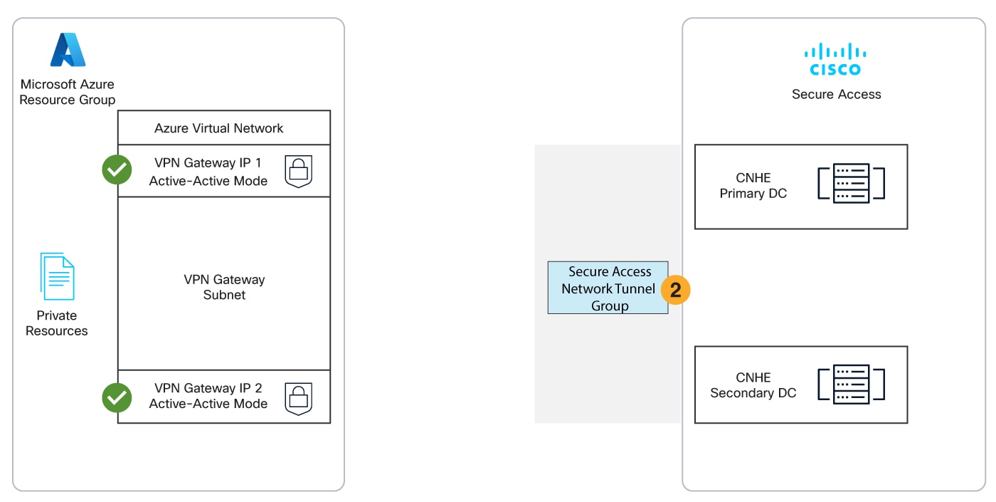
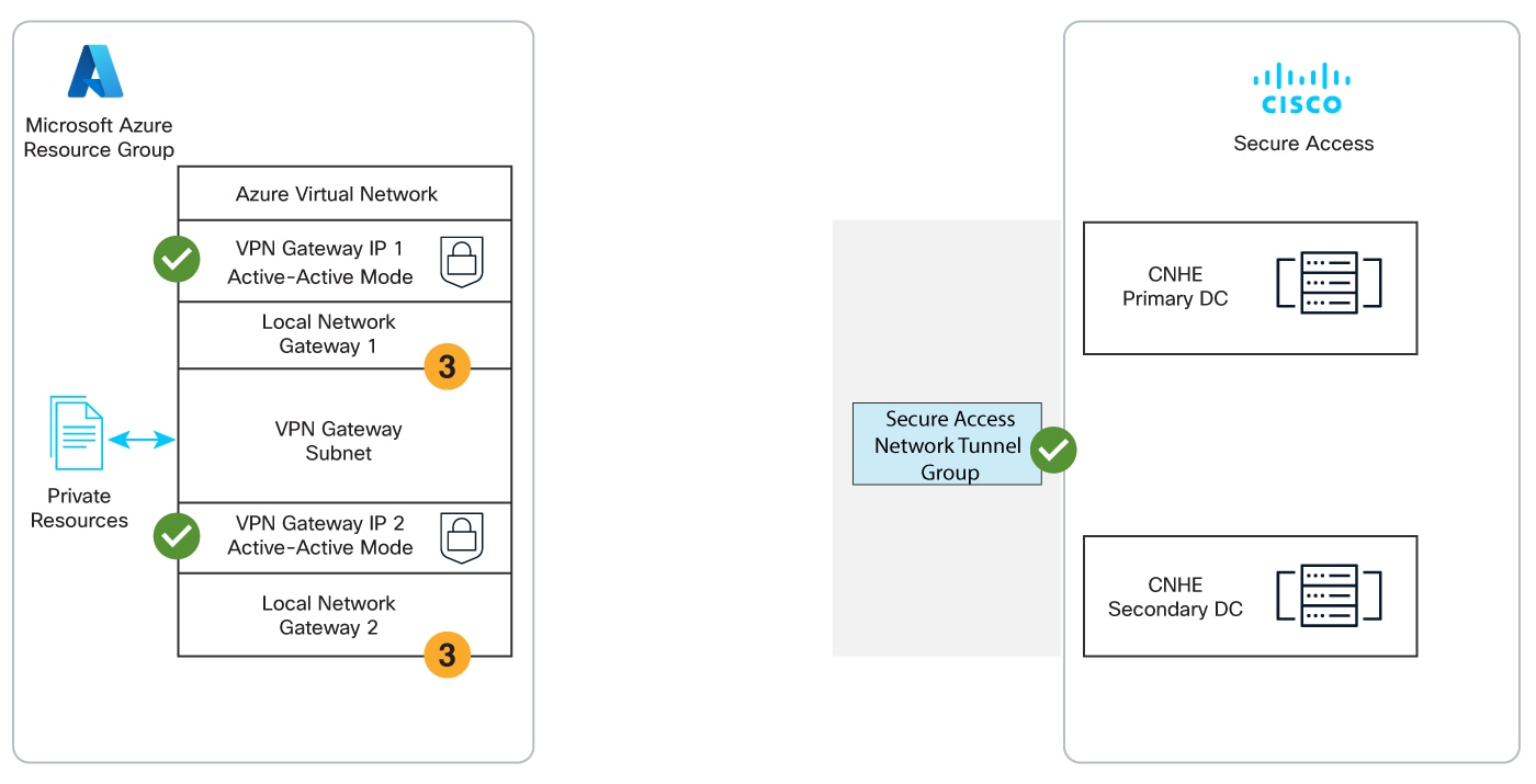
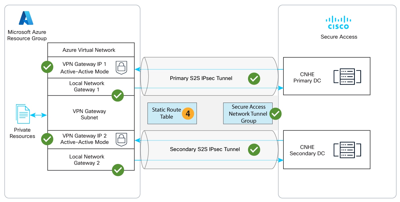
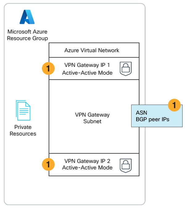
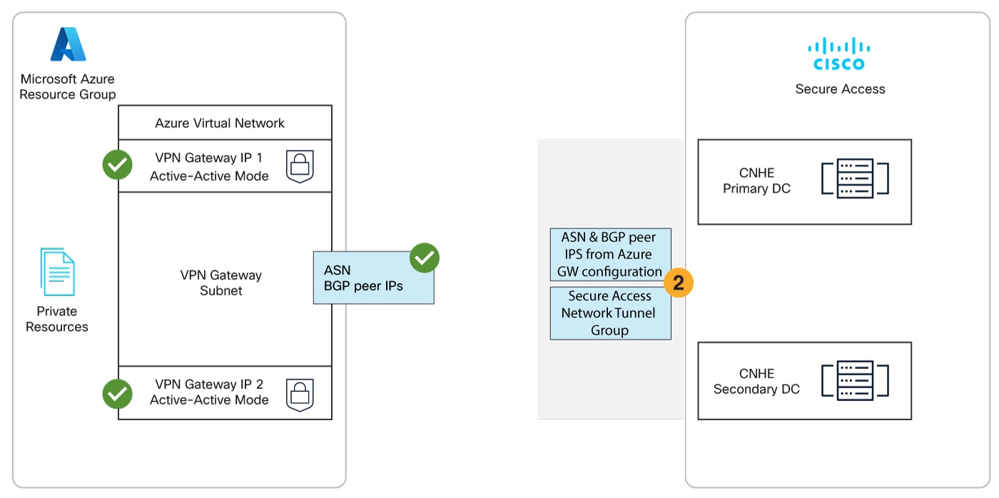
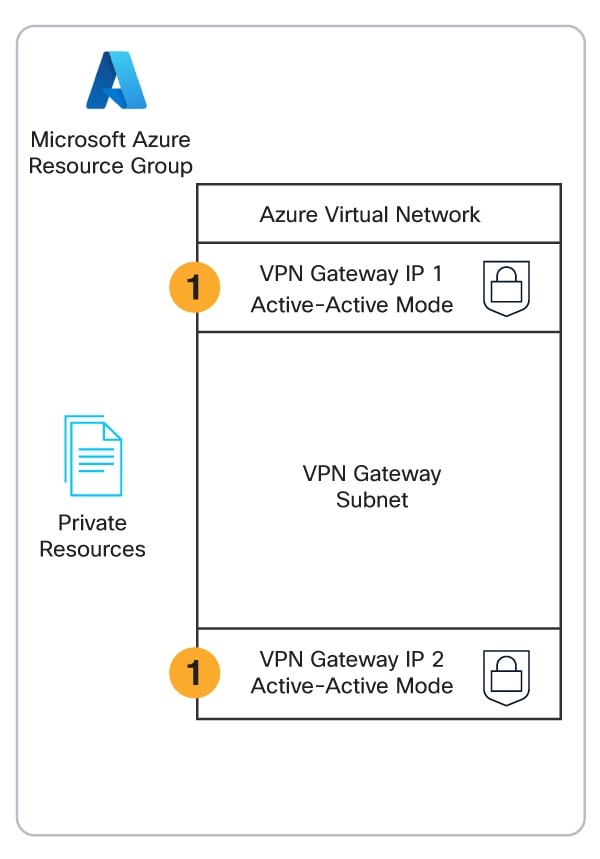
Microsoft Azure supports several methods of connecting to its VPN Gateway. The S2S VPN topology depends on components configured in the following order. Components in the diagram are numbered by order of configuration.

  1. An Azure virtual network with a VPN gateway in active-active mode for tunnel redundancy. In active-active mode, Azure provides two VPN gateway IPs that Secure Access can use to establish a network tunnel group. Traffic will use the primary tunnel. In the event of a tunnel failover, the switch to the secondary tunnel will be automatic, immediate, and without interruption.

  2. A Secure Access network tunnel group with two IPsec/IKEv2 tunnels and a pre-shared key (PSK) for connection with the Secure Access cloud native head end (CNHE) service.

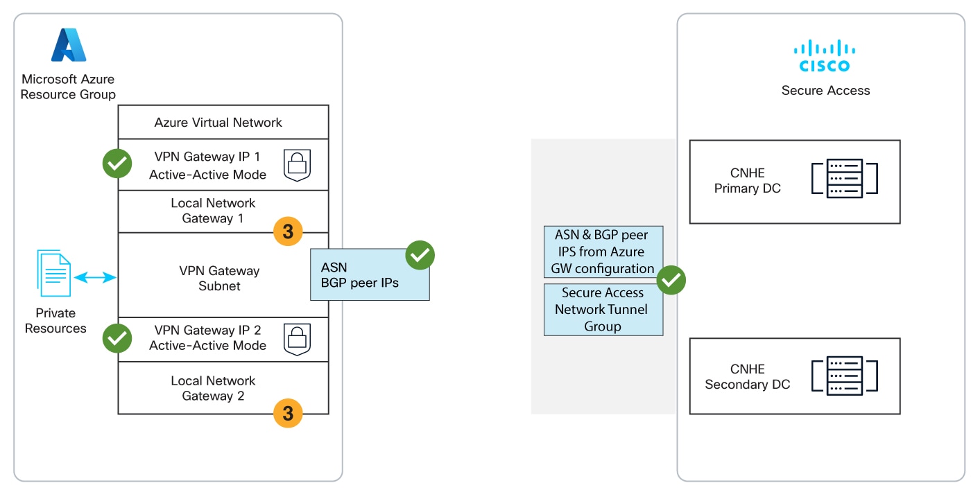
  3. Two local network gateways in Azure that establish S2S connections between the Azure VPN Gateway client and the Secure Access DC.


    Two local network gateways in Azure establishing S2S connections between the Azure VPN Gateway client and the Secure Access DC
  4. Branch and internet routing.

    • The static routing use case requires an Azure VPN Gateway route table.

    • The dynamic routing use case requires an Azure VPN Gateway autonomous system number (ASN) and Azure local network gateway BGP peer IP addresses.

For more information about VPN and tunnels in Secure Access, refer to Manage Virtual Private Networks and Manage Machine Tunnels.

Note

By default, the Perfect Forward Secrecy (PFS) setting is disabled in the Azure VPN portal; because the PFS is disabled, the Azure gateway client does not process the full proposal list as required by RFC 7296 when Secure Access is the platform to intiate the Child SA rekey. As a result the entire exchange is rejected and the CHILD SA rekey experiences a retry loop for a significant amount of time while the tunnel data plane is still active.

To safely incorporate the CHILD SA rekey we recommend following one of the following alternative configurations:

  • Shorten the Azure CHILD SA lifetime. In the Azure dashboard navigate to VPN Gateway > Connections and select your connection, then select IPsec / IKE policy. Locate the Default setting to Custom and then change the IPsec SA lifetime in seconds value to <3000.

  • Configure an alternate PFS setting. In the Azure dashboard navigate to VPN Gateway > Connections and select your connection, then select IPsec / IKE policy. Locate the Default setting to Custom and then change the PFS value. For example, set the new PFS value to a DH group.

More Information

For more information about Azure, refer to Microsoft documentation:

Note
Microsoft may update their documentation without notice.
Configure Azure S2S Tunnels with Static Routing

Follow these steps to deploy a site-to-site (S2S) VPN tunnel from Azure Virtual Network connects to Cisco Secure Access using an Azure route table for static routing to branch and internet destinations.

Use static routing for small, simple networks where predictable routes are needed and manual configuration is manageable. For more information, see Static Routing.

Before you begin

Prerequisites include the following.

  • A valid Cisco Secure Access account.

  • An Azure account with an active subscription.

Procedure

  1. In the Azure admin portal, navigate to your resource group and click Create.

  2. Search the marketplace for Virtual network, then click Create.

  3. Configure the virtual network.

    1. Basics: Select the Subscription and Resource group with the resources that you want to make available via the S2S VPN tunnel.

      Create virtual network page displaying fields to configure the subscription and resource group
    2. IP addresses: Configure a virtual network address with the IPv4 addresses and subnets you need. This example uses the range 10.255.0.0/16.

      Create virtual network page displaying fields to configure virtual network IP addresses
    3. Review the configuration and click Create.
      Azure will deploy the virtual network and update the dashboard when deployment is complete.
  4. Create the gateway subnet.


    Add a subnet page displaying fields to create a gateway subnet
    1. Navigate to Go to resource > Settings > Subnets.
    2. Click + Subnet.
    3. Subnet purpose: Choose Virtual Network Gateway.
    4. Enable Include an IPv4 address space (it is enabled by default).
    5. IPv4 address range will default to the address space you configured when you created the virtual network. This example uses the range 10.255.0.0/16.
    6. Starting address: This example uses 10.255.255.0.
    7. Size: This example uses /27 (32 addresses)
    8. Click Add.
  5. Create the virtual network gateway.

    1. Navigate to Overview > Resource group (click the name of your resource group) > + Create.
    2. Search the marketplace for Virtual network gateway, then click Create.
  6. Configure the virtual network gateway.


    Create network gateway page displaying fields to configure the virtual network gateway
    1. SKU: Choose VpnGw2AZ. For more information, see About gateway SKUs.
    2. Generation: Choose Generation2.
    3. Virtual network: Select the virtual network you created in the previous step.
    4. Public IP address: Chose Create new.
    5. Public IP address name: Enter a descriptive name for the primary IP address.
    6. Enable active-active mode: Choose Enabled.
    7. SECOND PUBLIC IP ADDRESS: Choose Create new.
    8. Public IP address name: Enter a descriptive name for the primary IP address.
    9. Configure BGP: Choose Disabled.
  7. Review the configuration, then click Create.


    Create network gateway displaying all configured fields for virtual network gateway

    Azure will deploy the virtual network gateway and update the dashboard with the two public IP address resources when deployment is complete.


    Overview section displaying the virtual network gateway deployment status
    Note
    To review your configuration after deployment is complete, navigate to Settings > Properties.

    Properties page displaying configuration details after deployment
  8. Step 1 - General Settings: Set Device Type to AZURE.

  9. Step 2 - Tunnel ID and Passphrase: Enter the primary and secondary public IPs from the Azure virtual network gateway and create a passphrase.

  10. Step 3 - Routing: Select Routing option > Static routing, then add all public and private IPv4 address ranges used internally for your Azure virtual network. This example uses the range 10.255.0.0/16.


    Routing section with an option to add IP address ranges for static routing
  11. Step 4 - Data for Tunnel Setup: Copy or download the primary and secondary tunnel IDs, data center (DC) IP addresses, and the passphrase you created.


    Data for Tunnel Setup page with options to copy or download CSV file containing network tunnel devices setup information
    Note
    This is the only time your passphrase will be displayed.
  12. In the Azure admin portal, navigate to Overview > Resource group > Click the name of your resource group > + Create.

  13. Search the marketplace for Local network gateway, then click Create.

  14. Configure the Basics tab of the first local network gateway.


    Create local network gateway page displaying fields for creating first local network gateway
    1. Select the Subscription and Resource group of your virtual network.
    2. Name: This example uses primary-dc.
    3. Endpoint: Select IP address
    4. IP address: For the first local network gateway, enter the Primary DC IP Address from Secure Access Step 4 - Data for Tunnel Setup.
    5. Address Space(s): Add one or more IP ranges for branch sites that will connect to the Secure Access network tunnel group. Address spaces should not overlap with other IP ranges in your network. This example uses 209.165.201.0/27.
      Azure does not support adding the address range 0.0.0.0/0 in the Address Space configuration for local network gateways. To work around this limitation, split the range into two separate entries:
      • 0.0.0.0/1

      • 128.0.0.0/1

  15. Review the configuration, then click Create.

    Azure will deploy the local network gateway and update the dashboard with the local network gateway resource when deployment is complete.
  16. Repeat the previous step to create the secondary local network gateway with the Secondary DC IP Address from Secure Access.


    Resources tab displaying the created local network gateway
  17. Create the S2S connection for the primary local network gateway.


    Create connection page displaying fields for creating the S2S connection for the primary local network gateway
    1. In the Azure admin portal, navigate to Overview > Resource group > Click the name of your resource group > Resources, then click the name of your virtual network gateway.
    2. Navigate to Connections, then click + Add.
    3. In the Basics tab, select the Subscription and Resource group of your virtual network.
    4. Connection type: Select Site-to-site (IPsec).
    5. In the Settings tab of the connection, select your virtual network gateway.
    6. Local network gateway: Select the primary gateway.
    7. Shared Key (PSK): Enter the passphrase configured for the Secure Access network tunnel group.
    8. IPsec / IKE policy: Select Custom.
    9. Select parameters for IKE Phase 1.
      • Encryption — Select AES256 (recommended).

      • Integrity/PRF — Select SHA256 (recommended).

      • DH Group — Select ECP384 (recommended).

    10. Select parameters for IKE Phase 2 (IPsec).
      • IPsec Encryption — Select AES256 (recommended).

      • IPsec Integrity — Select SHA256 (recommended).

      • PFS GroupNone is the default setting in Secure Access, but disabling this option fails to process the full proposal list and cuses the SHILD SA rekey experience to loop whie the data plane is still active. We recommend one of the following actions in the Azure dashboard instead:

        • Shorten the Azure CHILD SA lifetime. Navigate to VPN Gateway > Connections and select your connection, then select IPsec / IKE policy. Locate the Default setting to Custom and then change the IPsec SA lifetime in seconds value to <3000.

        • Configure an alternate PFS setting. Navigate to VPN Gateway > Connections and select your connection, then select IPsec / IKE policy. Locate the Default setting to Custom and then change the PFS value. For example, set the new FPS value to a DH group.

      Note
      For information about cipher parameters supported by Secure Access, see Supported IPsec Parameters. For information about cipher parameters supported by Azure, see Microsoft documentation on Default IPsec/IKE parameters.
    11. IPsec SA lifetime in seconds: Set to 14400.
    12. DPD timeout in seconds: Set to 30.
    13. Review the configuration, then click Create.
      Azure will deploy the S2S connection and update the dashboard when deployment is complete.
  18. Repeat the previous step for the secondary local network gateway.

  19. Both S2S VPN tunnels are now established with static routing between your Azure virtual network gateway and the Secure Access DC.


    Diagram illustrating S2S VPN tunnels established with static routing between an Azure virtual network gateway and the Secure Access DC
  20. In the Azure admin portal, navigate to Overview > Resource group (click the name of your resource group) > + Create.

  21. Search the marketplace for Route table, then click Create.

  22. Navigate to the Basics tab of the route table, then select the Subscription and Resource group of your virtual network.

  23. Review the configuration, then click Create.

    Azure will deploy the route table and update the dashboard when deployment is complete.
  24. Navigate to Overview > Resource group (click the name of your resource group) > Resources, then click the name of your route table.

  25. Click + Add.

  26. Configure a route.


    Add route page displaying fields for creating and configuring a route
    Along with your user-defined routes, add two routes to the Azure route table for the internet prefixes 0.0.0.0/1 and 128.0.0.0/1.
    1. Route name: This example uses Internet.
    2. Destination type: Select IP Addresses.
    3. Destination IP addresses/CIDR ranges: Enter the IP ranges for branch sites configured as address spaces for Azure local network gateways. This example uses 209.165.201.0/27.
    4. Next hop type: Select Virtual appliance.
    5. Next hop address: Enter the first IP address returned by the Azure CloudShell command shown below. In this example, the next hop address is 10.255.255.4.
      az network vnet-gateway show --resource-group \<Resource Group Name> -n \<VNET Gateway Name> | jq .bgpSettings.bgpPeeringAddress

      Azure CloudShell
      Note
      The CloudShell command returns the BGP peering addresses for the primary and secondary local network gateways.

      By creating a static route to the primary local network gateway connection, Azure will route all traffic to the primary DC via the primary S2S tunnel when both tunnels are up. When the primary tunnel is down, Azure will route all traffic to the secondary DC via the secondary S2S tunnel.

  27. Associate a subnet.

    1. Navigate to Settings > Subnets.
    2. Select the virtual network.
    3. Subnet: Select default.
    4. Click OK.

What to do next

Verify tunnel status in Secure Access

In Secure Access, navigate to Connect > Network Connections > Network Tunnel Groups and click the name of the network tunnel group to review the connection status with Azure.


Network Tunnels section displaying the connection status of the network tunnel group with Azure

Resources in your Azure virtual network are now protected by the site-to-site (S2S) IPsec/IKEv2 VPN tunnel with Cisco Secure Access.

For information about managing and monitoring your network tunnel group, see Manage Network Tunnel Groups.


Configure Azure S2S Tunnels with Dynamic Routing with BGP

Follow these steps to deploy a site-to-site (S2S) VPN tunnel from Azure Virtual Network connects to Cisco Secure Access using Azure BGP for dynamic routing to branch and internet destinations.

Use dynamic routing for large, complex networks with multiple connections where automatic route updates and optimal path selection are crucial, especially when dealing with internet connectivity or service provider traffic. For more information, see Dynamic Routing with BGP.

Before you begin

Prerequisites include the following.

  • A valid Cisco Secure Access account.

  • An Azure account with an active subscription.

Procedure

  1. In the Azure admin portal, navigate to your resource group and click Create.

  2. Search the marketplace for Virtual network, then click Create.

  3. Configure the virtual network.

    1. Basics: Select the Subscription and Resource group with the resources that you want to make available via the S2S VPN tunnel.

      Create virtual network page displaying fields to configure the subscription and resource group
    2. IP addresses: Configure a virtual network address with the IPv4 and IPv6 addresses and subnets you need. This example uses the range 192.168.0.0/16.

      Create virtual network page displaying fields to configure virtual network IP addresses
    3. Review the configuration and click Create.
    Azure will deploy the virtual network and update the dashboard when deployment is complete.
  4. Create the gateway subnet.


    Add a subnet page displaying fields to create a gateway subnet
    1. Navigate to Go to resource > Settings > Subnets.
    2. Click + Subnet.
    3. Subnet purpose: Select Virtual Network Gateway.
    4. Enable Include an IPv4 address space (it is enabled by default).
    5. Confirm IPv4 address range defaulted to the address space you configured when you created the virtual network. This example uses the range 192.168.0.0/16.
    6. Starting address: This example uses 192.168.255.0.
    7. Size: This example uses /27 (32 addresses)
    8. Click Add.
  5. Create the virtual network gateway.


    Create network gateway page displaying fields to create a virtual network gateway
    1. Navigate to Overview > Resource group (click the name of your resource group) > + Create.
    2. Search the marketplace for Virtual network gateway, then click Create.
  6. Configure the virtual network gateway.


    Create network gateway page displaying fields to configure the virtual network gateway
    1. SKU: Select VpnGw2AZ. For more information, see About gateway SKUs.
    2. Generation: Select Generation2.
    3. Virtual network: Select the virtual network you created in the previous step.
    4. Public IP address: Select Create new.
    5. Public IP address name: Enter a descriptive name for the primary IP address.
    6. Enable Enable active-active mode.
    7. SECOND PUBLIC IP ADDRESS: Select Create new.
    8. Public IP address name: Enter a descriptive name for the primary IP address.
    9. Enable Configure BGP.
    10. Autonomous system number (ASN): Enter an ASN that is not in use by your other branches and that is not reserved by Azure or IANA. This example uses ASN 64515. For more information, see Microsoft Azure documentation on BGP and routing.
    11. You do not need to enter custom Azure APIPA BGP IP addresses.
  7. Review the configuration, then click Create.

    Azure will deploy the virtual network gateway and update the dashboard with the two public IP address resources when deployment is complete.
    Overview section displaying the virtual network gateway deployment status
  8. To review your configuration after deployment is complete, navigate to Settings > Properties.


    Properties page displaying configuration details after deployment
  9. In Step 1 - General Settings: Set Device Type to AZURE.

  10. In Step 2 - Tunnel ID and Passphrase: Enter the primary and secondary public IPs from the Azure virtual network gateway and create a passphrase.

  11. In Step 3 - Routing:


    Routing section with an option to add ASN and IP address ranges for dynamic routing
    1. Select Dynamic routing.
    2. Device AS Number: Enter the ASN configured for the Azure virtual network gateway. This example uses 64515.
    3. BGP peer IP address 1 and 2: Enter two private IP address ranges (RFC1918). This example uses 10.255.255.254/32 and 10.255.255.255/32.
    Tip
    BGP peer IP address compatibility between Azure and Secure Access

    By default, Secure Access listens for BGP peer requests in the the APIPA address range 169.254.0.0/24. Azure does not initiate BGP connections to peers in the range 169.254.0.0/16. To work around this limitation, configure the Secure Access tunnel group to listen for BGP peer requests from two RFC1918 private IP ranges. These ranges should not overlap with 169.254.0.0/16 or with ranges assigned to your other branches that connect to Secure Access.

  12. In Step 4 - Data for Tunnel Setup: Copy or download the primary and secondary tunnel IDs, data center (DC) IP addresses, and the passphrase you created.


    Data for Tunnel Setup page with options to copy or download CSV file containing network tunnel devices setup information
    This is the only time your passphrase will be displayed.
  13. In the Azure admin portal, navigate to Overview > Resource group (click the name of your resource group) > + Create.

  14. Search the marketplace for Local network gateway, then click Create.


    Create local network gateway page displaying fields for creating first local network gateway
  15. Configure the Basics tab of the first local network gateway.

    1. Select the Subscription and Resource group of your virtual network.
    2. Enter a Name. This example uses primary-dc.
    3. Endpoint: Select IP address.
    4. IP address: For the first local network gateway, enter the Primary DC IP Address from Secure Access Step 4 - Data for Tunnel Setup.
    5. Leave Address space(s) blank.
  16. Configure the Advanced tab of the first local network gateway.


    Create local network gateway page displaying fields to configure in the Advanced tab
    1. Configure BGP settings: Select Yes.
    2. Autonomous system number (ASN): Enter the Peer (Secure Access) BGP AS number from the Secure Access network tunnel group created earlier. This example shows the ASN 32644. You can also find this ASN in the Summary section of your network tunnel group in Secure Access.
    3. BGP peer IP address: For the first local network gateway, enter the BGP peer IP address 1 that you configured in Secure Access Step 3 - Routing. You can also find the BGP peer IP address in the Summary section of your network tunnel group in Secure Access.
  17. Review the configuration, then click Create.


    Summary page displaying all configured fields for the network tunnel group
    Azure will deploy the local network gateway and update the dashboard with the local network gateway resource when deployment is complete.
  18. Repeat steps 3 and 4 to create the secondary local network gateway with the BGP peer IP address 2 and the Secondary DC IP Address from Secure Access.


    Resources tab displaying the created local network gateway
  19. Create the S2S connection for the primary local network gateway.

    1. In the Azure admin portal, navigate to Overview > Resource group (click the name of your resource group) > Resources, then click the name of your virtual network gateway.
    2. Navigate to Connections, then click + Add.
    3. Navigate to the Basics tab, then select the Subscription and Resource group of your virtual network.
    4. Connection type: Select Site-to-site (IPsec).
    5. Navigate to the Settings tab of the connection, then select your virtual network gateway.
    6. Local network gateway: Select the primary gateway.
    7. Shared Key (PSK): Enter the passphrase configured for the Secure Access network tunnel group in step 2.
    8. Enable BGP: Check the box.
    9. IPsec / IKE policy: Select Custom.
    10. IKE Phase 1: The following configuration is recommended.
      • Encryption: GCMAE256.

      • Integrity/PRF: SHA256.

      • DH Group: ECP384.

      • For information about cipher parameters supported by Secure Access, see Supported IPsec Parameters. For information about cipher parameters supported by Azure, see Microsoft documentation on Default IPsec/IKE parameters.

      • IPsec SA lifetime in seconds: <3000. Note that any value less than 300 can cause the CHILD SA Rekey to enter a retry loop while the data plane is still active.

      • DPD timeout in seconds: 30


    Create connection page displaying fields for creating the S2S connection for the primary local network gateway
  20. Review the configuration, then click Create.

    Azure will deploy the S2S connection and update the dashboard when deployment is complete.
  21. Repeat step 6 for the secondary local network gateway.


    Diagram illustrating S2S VPN tunnels established with static routing between an Azure virtual network gateway and the Secure Access DC
    Both S2S VPN tunnels are now established with dynamic routing with BGP between your Azure virtual network gateway and the Secure Access DC.
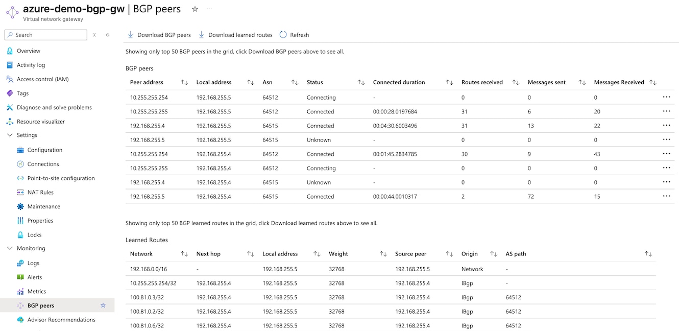
  22. In the Azure admin portal, navigate to Overview > Resource group (click the name of your resource group), then click the name of your virtual network gateway.

  23. Navigate to Settings > BGP peers to review the table of Learned Routes received by your Azure virtual network gateway and the Secure Access service.

  24. In Secure Access, navigate to Connect > Network Connections > Network Tunnel Groups and click the name of the network tunnel group to review the connection status with Azure.


    The Azure S2s Azurebgp 13 Csa Ntg interface.
  25. Under Network Tunnels, click a tunnel name to review Routing details. Client Routes show routes advertised by Azure to Secure Access via BGP. Cloud Routes show routes advertised by Secure Access to Azure via BGP.


    Primary 1 page displaying routing details, including client routes and cloud routes advertised by Azure to Secure Access via BGP
    Branch access to resources in your Azure virtual network is now protected by the site-to-site (S2S) IPsec/IKEv2 VPN tunnel with Cisco Secure Access.

What to do next

Verify tunnel status in Secure Access

In Secure Access, navigate to Connect > Network Connections > Network Tunnel Groups and click the name of the network tunnel group to review the connection status with Azure.

Network Tunnels section displaying the connection status of the network tunnel group with Azure

Resources in your Azure virtual network are now protected by the site-to-site (S2S) IPsec/IKEv2 VPN tunnel with Cisco Secure Access.

For information about managing and monitoring your network tunnel group, see Manage Network Tunnel Groups.