Cisco Crosswork Planning Design 7.2.x User Guide

PDF

Cisco Crosswork Planning Design 7.2.x User Guide

States of plan objects

Want to summarize with AI?

Log in

Lists and describes the states of plan objects, including their definitions and how these states appear in the network summary tables.


The state of a plan object affects the simulation and determines whether that object is operational.

There are three states available in Cisco Crosswork Planning plan objects.

  • Failed: Identifies whether the object is failed.

  • Active: Identifies whether the object is available for use in the simulated network. For example, an object might be unavailable because it has been set administratively down.

  • Operational: Identifies whether an object is operational. For example, an object might be non-operational because it is failed, is inactive, or because other objects on which it depends are not operational.

Columns in network summary tables

The Failed and Active columns in the network summary tables show a visual representation of their status. Likewise, the Operational column shows the calculated operational state. In each column, "true" indicates that the object is in that state. "false" indicates that it is not. The value of "true" or "false" for the Active state in the Interfaces table reflects the status of the associated circuit. The plot shows graphical representations of these states with either a white cross or a down arrow displayed inside a red circle.

These plan objects have the Active, Failed, and Operational columns:

  • Circuits

  • Nodes

  • Sites

  • Ports

  • Port circuits

  • SRLGs

  • External endpoint members


Failed state

A Failed state is a condition in network simulations where objects such as interfaces or circuits experience failure.

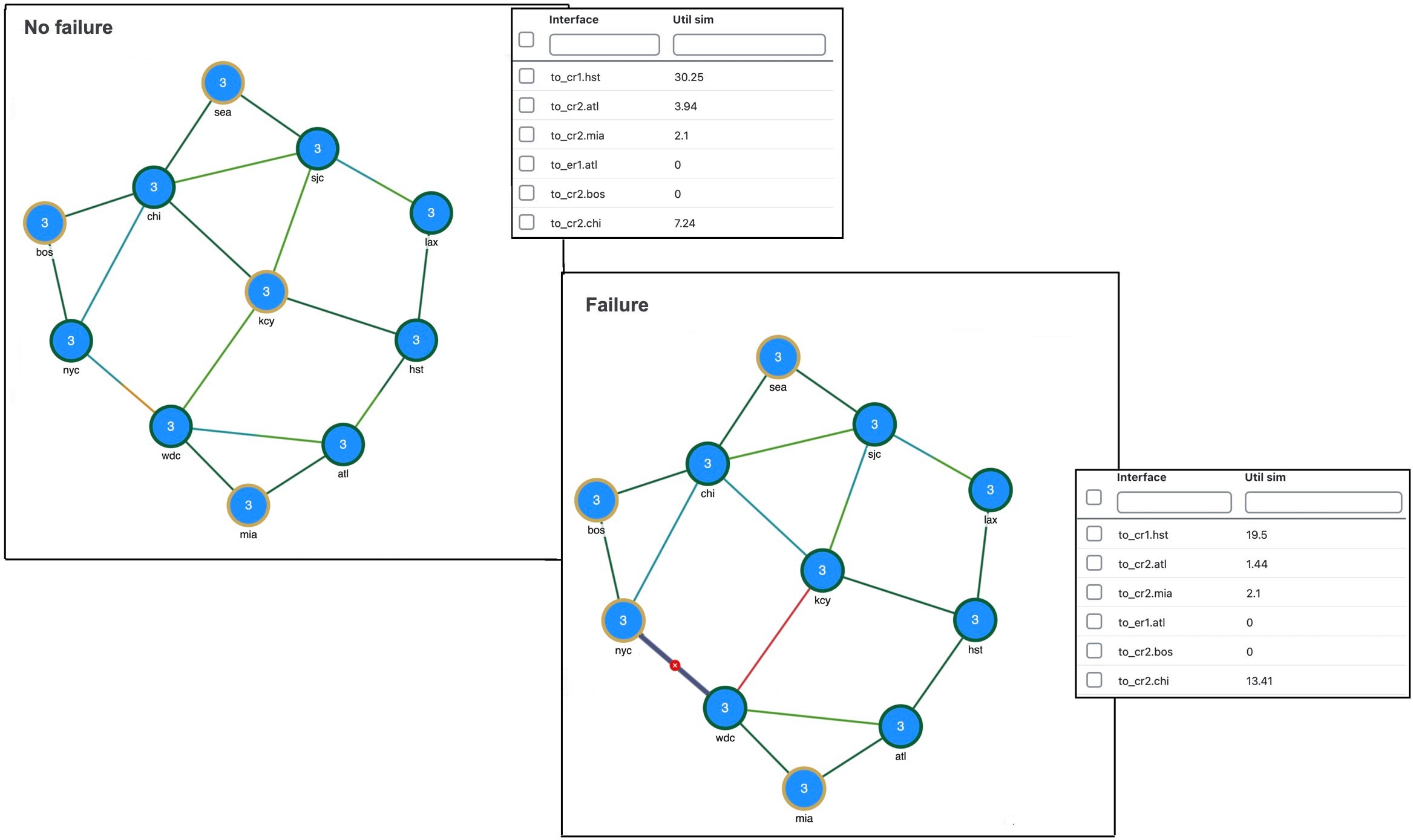
The quickest way to see the effects of failures in a simulated traffic view is to have demands in place, and then fail an object. When a failure occurs, the simulation reflects the changes immediately.

If you select an interface to fail, you are actually failing its associated circuit. To view the complete list of objects that can be failed, refer to the list in States of plan objects.

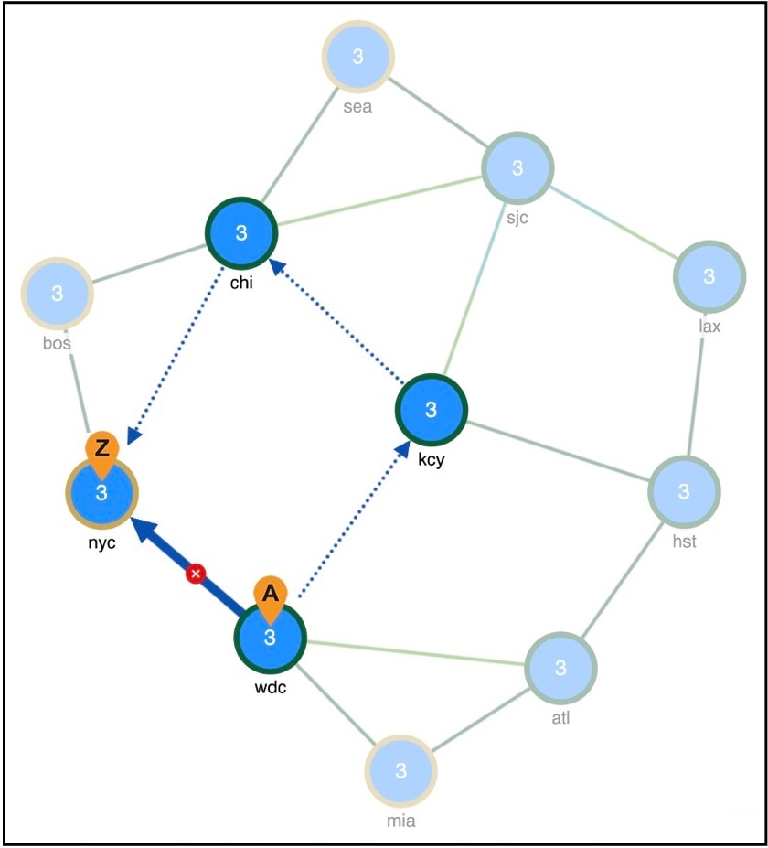
Figure 1. Failed circuit
Failed circuit example
Figure 2. Reroute of demand around a failed circuit
Reroute of demand around a failed circuit

Disabling demand rerouting

To specify that a demand should not reroute around failures, uncheck the Reroutable check box in the demand’s Edit page. This can be used as a way of including L2 traffic on an interface. For example, a one-hop, non-reroutable demand can be constructed over the interface to represent the L2 traffic. Other reroutable demands can be constructed through the interface as usual. If the interface fails, the L2 traffic is removed and the L3 traffic reroutes.


Fail or recover plan objects

Use this task to update the operational status of one or more network objects to simulate failures or perform recovery.

Before you begin

This table lists the objects that you can fail or recover.

Interfaces

Ports

Circuits

Port circuits

Nodes

SRLGs

Sites

External endpoint members

Procedure

1.

To fail a single object, click > Fail under the Actions column.

2.

After failing an object, the menu option changes to Recover. Use this option to recover the failed objects.

3.

Follow these steps to fail or recover multiple objects:

  1. Select the required objects.

  2. Click More actions > Fail or More actions > Recover to fail or recover objects.

Note

You can

  • select all objects, and fail or recover them

  • filter objects, and fail or recover them, or

  • select objects from the network plot, and fail or recover them.

The failed object is marked with a red circle and white X in the network plot (for example, refer to Failed circuit). The icon disappears when you recover the object.


Protect circuits from SRLG failures

You can protect circuits from being included in SRLG failures and SRLG worst-case analysis. However, there are differences in behavior, such as:

  • These circuits do not fail when an SRLG fails individually. However, they will fail if the circuit itself fails.

  • These circuits are protected from being included in Simulation analysis regardless of whether they are in an SRLG.

Note

This setting does not affect the routing of FRR SRLGs. For information on FRR SRLGs, refer to Optimize RSVP-TE Routing.

Procedure

1.

Open the plan file (refer to Open plan files). It opens in the Network Design page.

2.

Set the Protected property for circuits.

  1. In the Network Summary panel, select one or more circuits from the Circuits table.

  2. Click Edit icon.

    Note

    If editing a single circuit, you can also use the > Edit option under the Actions column.

  3. In the State field, check the Protected check box.

  4. Save the changes.

3.

Set the Network options property for protecting circuits included in SRLGs.

  1. Click in the toolbar or choose Actions > Edit > Network options.

  2. In the Redistribute routes across IGP process section under the Simulation tab, check the Exclude protected circuits from SRLG failure check box.

  3. Save the changes.


Active state

An active state indicates whether an object is available for measured or simulated traffic calculations.

An object can be inactive for several reasons:

  • It is administratively down.

  • It is a placeholder. For example, you might be planning to install an object and want its representation in the network plot.

  • It exists in a copied plan but was not present in the original discovered plan.

You can simultaneously change the active state of one or more objects. If you change the active state of an interface, you change its associated circuit.

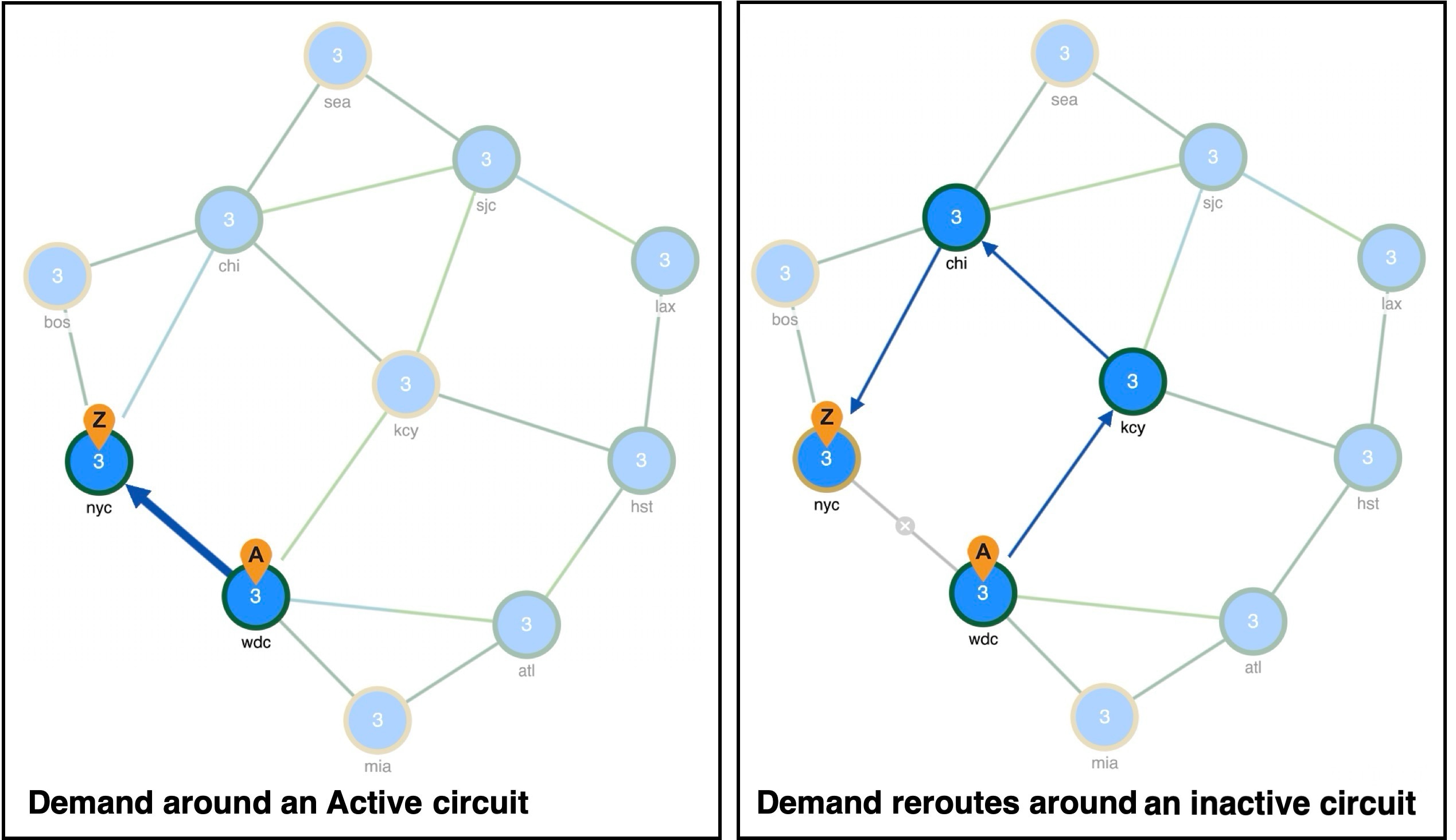
Like failures, changing an object from active to inactive immediately affects demand routing and the Util sim column in the Interfaces tables (Inactive circuit).

Figure 3. Inactive circuit
Inactive circuit

Objects that can be set as Active

This is the list of objects that can be set as Active:

  • Circuits

  • Nodes

  • Sites

  • Ports

  • Port circuits

  • SRLGs

  • External endpoint members

  • Demands

  • LSPs

  • LSP paths


Set objects to Active or Inactive state

Complete these steps to set the state of the objects to Active.

Before you begin

Make a note of the list of objects whose State can be set to Active or Inactive by referring to the Active State section.

Procedure

1.

Open the plan file (refer to Open plan files). It opens in the Network Design page.

2.

In the Network Summary panel, select one or more objects from their respective tables.

3.

Click Edit icon.

Note

If editing a single object, you can also use the > Edit option under the Actions column.

4.

In the State field, check the Active check box to toggle it on or off.

A check mark indicates the object is active. To make it inactive, clear the check box.

5.

Save the changes.

The system updates the selected objects to active or inactive, reflecting their current state in your network design. If an object is active, the Active column in the Network summary table displays "true" for that object.

Operational state

The operational state identifies whether the object is functioning. You cannot set an operational state. It is automatically calculated based on the failed and active states.

  • Any object that is failed or inactive is operationally down.

  • If the object relies on other objects to function, its operational state matches the state of those objects.

This table lists how failure or inactivity of objects impacts operational status.

If this object fails or is inactive

These objects are operationally down

Node

circuits connected to the failed node

Site

sites, nodes, and circuits within the failed site

SRLG

objects within the failed SRLG

Port

port circuits that contain the failed port