Cisco Crosswork Planning Design 7.2.x User Guide

PDF

Cisco Crosswork Planning Design 7.2.x User Guide

RSVP-TE optimization input properties

Want to summarize with AI?

Log in

Lists and describes the LSP and interface input properties required by the RSVP-TE optimization tool.


The RSVP-TE optimization tool (found under Actions > Tools > RSVP LSP optimization > RSVP-TE optimization) uses the LSP and interface input properties listed in Table 1 to execute its optimization calculations.

These properties, which are specified in user columns in the LSPs and Interfaces tables, can be created in one of the two ways:

  • Automatic creation: Use the tool to automatically create the properties if they do not exist. The selections made in the Specify LSP groups, LSP parameters, and Interface parameters areas populate the input properties.

    Figure 1. RSVP-TE optimization options
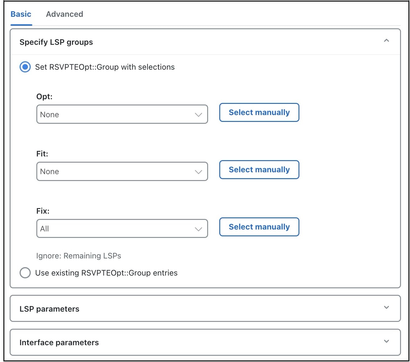
    RSVP-TE optimization options

    Example 1: If you choose LSPs to optimize, to fit, and to fix (in the Specify LSP groups section), the tool creates the RSVPTEOpt::Group column in the LSPs table and sets this property to the appropriate values for each LSP (Opt, Fit, Fix). Existing properties are updated if values change.

    Example 2: If you select to set the interface bandwidth bound based on the Resv BW property (in the Interface parameters section), the tool creates the RSVPTEOpt::BWBound column in the Interfaces table and for each interface, copies the Resv BW value to it. Existing properties are updated if the new value changes.

  • Manual creation: Before running the tool, manually create the input properties as user columns in the LSPs and Interfaces tables. When running the tool, you must then select the Use existing RSVPTEOpt:: property_name option. This is useful if you want to configure specific values rather than using existing properties and values. For information on creating user-defined columns, refer to Table 1.

    Note
    As the resulting network model can potentially reset properties that can be used as input to optimizations, it is a best practice to run the optimization only on plan files or LSPs that have not yet been optimized. For example, by default, Cisco Crosswork Planning resets the LSP setup BW property to 0 after optimizing LSPs, which could impact subsequent optimizations.

RSVPTEOpt input parameters

Table 1. RSVPTEOpt input parameters

Table

Input property

Description and values used to create the Input property

LSPs

RSVPTEOpt::Group

LSP optimization group.

The input property is derived based on your entries in the Specify LSP groups area unless you select to use the existing RSVPTEOpt::Group property. Values are Opt, Fit, or Fix. If the value is not defined, it is set to None.

For more information, refer to LSP group options.

RSVPTEOpt::BWReq

The bandwidth required by each LSP that is being optimized.

The input property is derived from the Setup BW, Traff meas, or Traff sim properties in the LSP properties section, unless you specify to use the existing RSVPTEOpt::BWReq value.

For more information, refer to Optimization parameters.

Interfaces

RSVPTEOpt::BWBound

Sum total of LSP bandwidth routed over the interface should not exceed this value.

The input property is derived from the Resv BW, Capacity, or Capacity sim properties in the Interface properties section, unless you specify to use the existing RSVPTEOpt::BWBound value.

For more information, refer to Optimization parameters.

RSVPTEOpt::Metric

Metric value used in the shortest path calculations.

The input property is derived from either the TE metric or Delay property in the Interface properties section, unless you specify to use the existing RSVPTEOpt::Metric value.

For more information, refer to Optimization parameters.


LSP group options

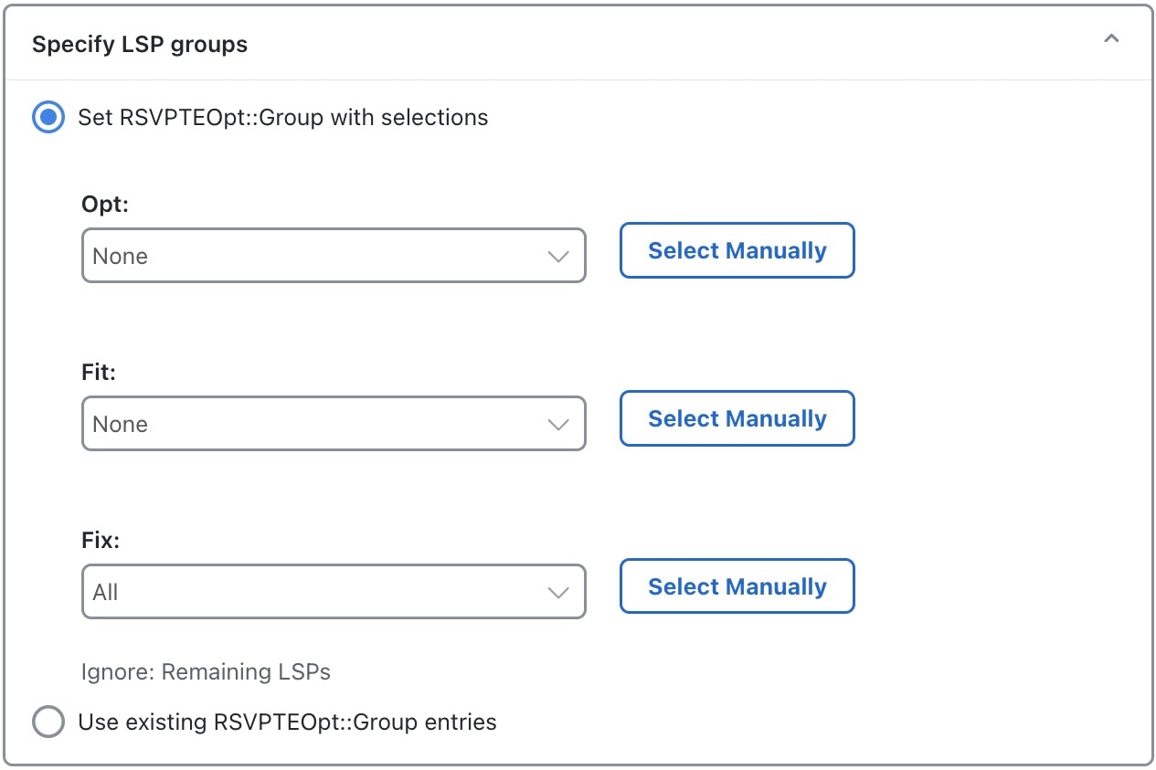
The LSP group options determine the optimization treatment of LSPs using the RSVP-TE optimization tool. To determine how and whether LSPs are optimized, select them from the Specify LSP groups section. If an LSP belongs to multiple groups, its optimization is determined by the first group in which it appears.

Figure 2. LSP groups
Select LSP groups options

Select the Set RSVPTEOpt::Group with selections radio button and set these properties:

  • Opt: Explicitly routes or reroutes the LSPs to minimize their path length, while respecting the bandwidth bounds specified for the interfaces. The RSVP-TE optimization tool changes the LSP path as much as needed to find the optimal route. First, it tries to set the LSP to its shortest path, which is defined by the interface Metric parameter. The LSP is moved away from the shortest path only if needed due to congestion.

    Setting all LSPs to this option is useful when trying to achieve global optimization on all LSPs.

  • Fit: Reroutes the LSPs only as necessary to respect specified bandwidth bounds on the interfaces, while accommodating the Opt group. If there is currently no explicit route or if the route is incomplete, treats like Opt LSPs.

    This option is useful when attempting tactical congestion mitigation, where it is desirable to move as few LSPs as possible to remove existing congestion.

    A combination of Opt and Fit, or a combination of Opt and Fix is useful for targeting the optimization of new LSPs.

  • Fix: Does not reroute the LSPs, but includes them in the optimization calculations.

Selection behavior

LSPs that are not selected are ignored. They maintain their original configuration and are not considered in optimization calculations. This is useful for network regions that do not interfere with optimizations. Note that if measured interface traffic is used in optimizations, traffic contributions from the ignored LSPs to this measured traffic may affect the results.

You can set each of the Set RSVPTEOpt::Group with selections to None, All, or manually selected. This configuration allows you to assign specific LSPs to different optimization treatments.


Optimization parameters

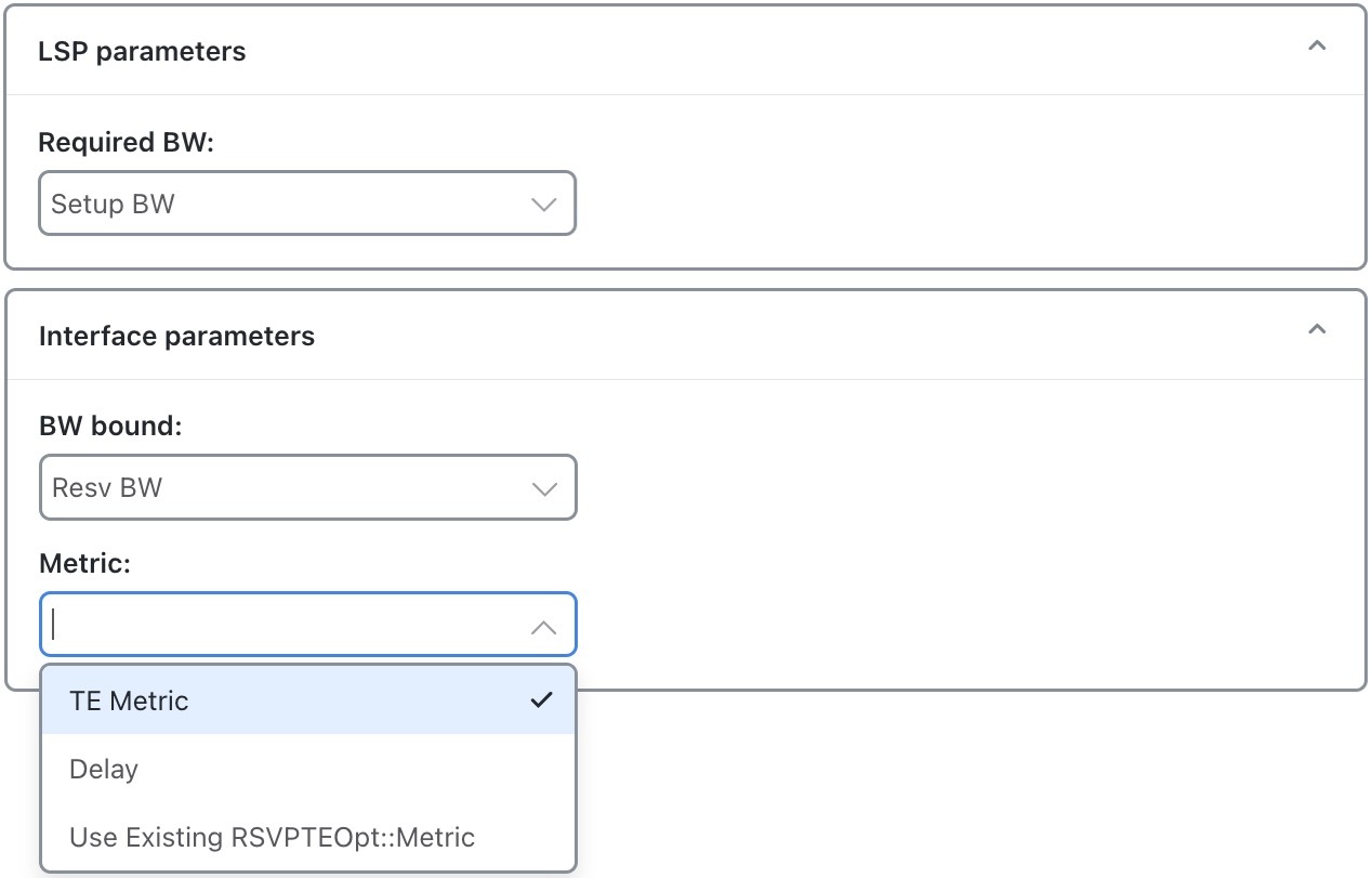
Optimization calculations are based on two sets of parameters that define how much bandwidth the LSPs require, how much bandwidth the interfaces have available for these LSPs, and which metric to use for shortest path.

LSP optimization parameters

The LSP parameters and Interface parameters sections offer these options:

Table 2. Optimization input parameters
Parameter Description Options
Required BW This LSP parameter specifies how to determine the bandwidth required for primary LSP paths.
  • Setup BW

  • Traff meas

  • Traff sim

BW bound This interface parameter indicates the bandwidth available on interfaces to carry LSPs. The system tries to route LSPs without surpassing this bound, but exceeds it if necessary.
  • Resv BW

  • Capacity

  • Capacity sim

Metric This interface parameter defines the metric used for shortest path calculations.
  • TE metric

  • Delay


Disjoint groups

Two LSP paths are disjoint if they do not route over common objects. These objects are configurable and can be circuits, nodes, sites, or SRLGs.

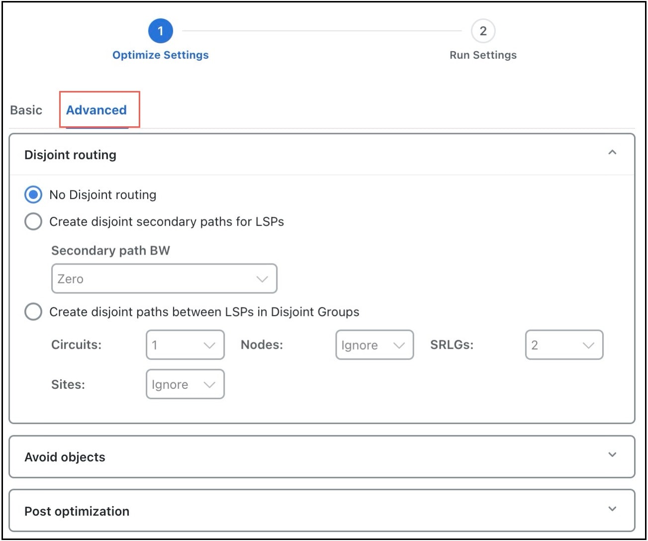
In the Advanced tab, you can create disjoint paths or use existing disjoint paths.

Figure 3. RSVP-TE LSP optimization advanced options
Screenshot of the Advanced tab showing RSVP-TE LSP disjoint path configuration options, including parameters for object type selection, bandwidth settings, and disjoint group definitions.

These are the available disjoint routing options:

  • No disjoint routing: Does not create disjoint secondary paths and does not enforce any disjointness on primary paths.

  • Create disjoint secondary paths for LSPs: Creates secondary LSP paths that are disjoint from the primary LSP paths.

    Additionally, specifies whether to include secondary paths in the optimization. If set to Zero, their bandwidths are set to 0 and are not included. Otherwise, their required bandwidths are set to be the same as the primary paths, and they are included in the optimization.

  • Create disjoint paths between LSPs in Disjoint Groups: Creates disjoint paths between LSPs that are in disjoint groups.


Avoidance constraints

Avoidance constraints specify network elements that should be excluded from the optimization of LSPs.

The Avoid objects section in the Advanced tab (RSVP-TE LSP optimization advanced options) lets you select Nodes, Interfaces, and SRLGs to be avoided when optimizing LSPs.

The available object types are:

  • Nodes: LSPs are created to route away from the Nodes selected. The default value is None.

  • Interfaces: LSPs are created to route away from the Interfaces selected. The default value is None.

  • SRLGs: LSPs are created to route away from the SRLGs selected. The default value is None.