Cisco Crosswork Planning Design 7.2.x User Guide

PDF

Cisco Crosswork Planning Design 7.2.x User Guide

Simulate routing with external endpoints

Want to summarize with AI?

Log in

Describes how routing simulations select endpoint members by priority and availability, redistribute traffic during failures, and apply BGP routing policies for external AS members.


Note

Although this section describes demands as being sourced from an external endpoint, the same methodology holds true if a demand’s destination is an external endpoint.

Summary

The simulation of routing with external endpoints involves selecting members based on priority and availability, redistributing traffic upon failures, and applying BGP routing policies for external AS members.

The key components involved in the process are:

  • External endpoint members: Nodes, ASes, or external nodes that serve as traffic sources or destinations.

  • Priority levels: Determine the order in which members are used.

  • BGP routing policy: Governs routing when members are external ASes.

Workflow

The process involves these stages:

  1. Members with the highest priority (lowest number) are used as the demand’s source. For example, if the external endpoint has two members with a priority of 1, the demand is sourced from both members provided they are available.
  2. If some members are not available, their traffic is evenly redistributed to the other top priority members.
  3. If none of the top priority members are available to source the traffic but there are next-priority members available, Step 1 is repeated for the next priority external endpoint members.
  4. If all members with the same priority fail, the traffic is routed according to the next priority in the sequence.
  5. If a failure occurs that does not affect the external endpoint member’s ability to send or receive traffic, then traffic is rerouted as usual without a need to use the additional members.
  6. If an external endpoint member is an external AS, with or without a node specified, the routing for that member is based on the BGP routing policy set by the AS relationships. The distribution of traffic between external endpoints with the same priority is the same as that for node members.
Traffic distribution

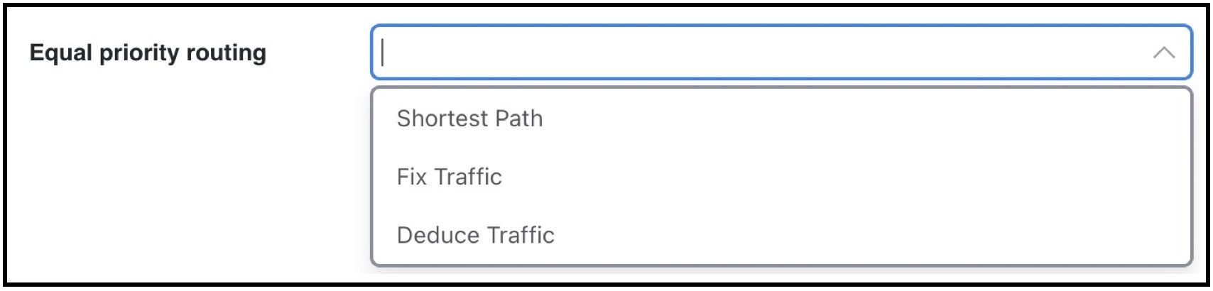
The traffic distribution through these demands is based on the Equal priority routing property, and if applicable, the Traffic balance (%) property is used to define the external endpoint members.

Traffic distribution setting
  • If there is only one member and it is defined as Shortest Path, the demand takes the shortest path as defined by the IGP metrics.

    If the Traffic balance (%) values are empty for all routable demands, traffic is routed and equally load balanced across the demands with the shortest IGP paths. In the case of multiple internal ASes, the shortest IGP route is the shortest route in the first AS the demand enters.

  • If multiple members of the same priority are set to Shortest Path, the demand takes the path with the shortest IGP path. If all interfaces between the source members and the destination have the same shortest IGP paths, then the traffic is load balanced equally across them.

  • If one or more members of the same priority have their Equal priority routing property set to Fix Traffic or Deduce Traffic, the demand traffic is split according to each member’s Traffic balance (%) value.

    • If the Traffic balance percentages across sources with the same priority sum to less than 100%, the overall demand traffic is decreased to that percentage.

    • If an external endpoint member of the same priority fails, the traffic on the remaining members increases in proportion, so that the same amount of traffic is still routed.

Example

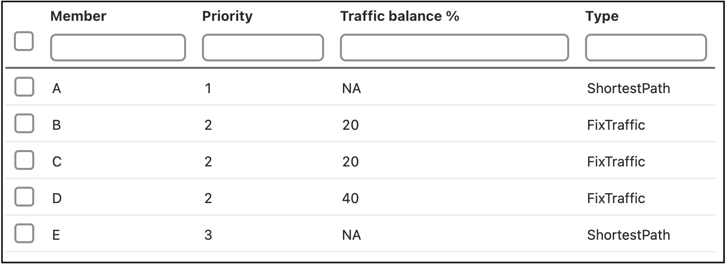
Consider Node A has failed. Nodes B, C, and D each with priority 2 and Fix Traffic type. Their traffic balances are 20%, 20%, and 40%, respectively.

The demand has 1000 Mbps of traffic.

  • With Node A failed, the demand routes 200 Mbps traffic through node B, 200 Mbps through C, and 400 Mbps through D, totaling 800 Mbps.

  • If Node D fails, the demand routes 400 Mbps traffic through Node B and 400 through C. If Node B fails too, the entire 800 Mbps is routed through C.

  • If all three priority 2 members fail, 1000 Mbps is routed through node E, which is the priority 3 member.