Describes how to create and visualize MPLS LSPs within the network design interface.
To simulate MPLS LSPs in the network, you must first set up the LSPs to be routed. Use this task to create and visualize LSPs from the UI.
Procedure
-
From the toolbar, choose .
Alternatively, in the Network Summary panel on the right side, click
 > LSPs in the LSPs tab.
The LSPs tab is available under the More tab. If it is not visible, then click the Show/hide tables icon (
 ) and check the LSPs check box.
 -
To visualize the LSP in the network plot, select the LSP from the LSPs table. They appear in the plot as purple arrows.
Figure 1. LSP visualization 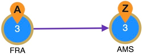
-
To add a mesh of LSPs between the selected nodes, use any of these options:
-
From the toolbar, choose .
-
In the Network Summary panel on the right side, click
> LSP mesh in the LSPs tab.
-
-
To filter to related information such as related interfaces, source and destination nodes, demands, or LSP paths, select the LSP, click
 , and choose the appropriate option.