Cisco Crosswork Planning Design 7.2.x User Guide

PDF

Cisco Crosswork Planning Design 7.2.x User Guide

Fast Reroute (FRR) simulations

Want to summarize with AI?

Log in

Explains how Fast Reroute (FRR) simulations work, including FRR fundamentals, routing during failures, protection mechanisms, and simulation outcomes.


A Fast Reroute (FRR) simulation is a network analysis technique that

  • models the behavior of Label Switched Paths (LSPs) under failure scenarios

  • evaluates how locally protected LSPs reroute traffic using pre-signaled FRR LSPs or bypass tunnels, and

  • measures restoration performance, often aiming for a 50 millisecond recovery.

Cisco Crosswork Planning simulates a Fast Reroute convergence mode using FRR LSPs. If a failure occurs in the route of a protected RSVP-TE LSP, a presignaled FRR LSP (or bypass tunnel) forwards traffic locally around the point of failure, typically from the node just before the failure to a node downstream. This restoration mechanism gives the source node (head-end) of the FRR LSP time to re-establish an alternate route around the failure. This period is sometimes described as the 50 millisecond behavior of the network because FRR restoration ideally becomes effective within approximately 50 milliseconds of a failure.

Routing of LSPs and demands in FRR simulations differs from full convergence simulations:

  • The source node of the protected LSP does not reroute the traffic. If a failure occurs on a node or circuit (link) within the LSP path, the routing occurs as described in these steps:

    • If an FRR LSP exists to protect a failed node or circuit, the protected LSP continues to be routed, but its new path includes the FRR LSP route that redirects the traffic around the failure. This traffic enters the FRR LSP’s source node just prior to the failure and rejoins the protected LSP path after the failure at the FRR LSP’s destination node.

    • If the LSP is not protected by an FRR LSP, then the LSP traffic is not routed.

  • Since there is no IGP reconvergence, demands through unrouted LSPs are unrouted. Additionally, demands through failures outside of these LSPs are not routed.

FRR fundamentals

This section summarizes key properties and terms, and how FRR LSPs are visualized in the network plot.

Objects and properties

Note
FRR LSPs appear in the same table as the regular LSPs and are identified in the Metric type column as FRR.
Table 1. Objects and properties

Object

Type

Column

Description

LSP

FRR LSP

FRR interface

Designated interface to be avoided by the FRR LSP.

FRR type

Type of FRR protection: Link or Node.

Autoroute

Forwarding Adjacency

FRR enabled

Marks an LSP to be protected by FRR LSPs.

Interface

na

FRR enabled

Marks an interface to be protected by FRR LSPs. This property is required if an interface is to be used when running the FRR LSPs initializer.

Terms

  • Protected interface: An interface that is avoided when using FRR LSPs.

  • Protected LSP: An LSP that would be rerouted through FRR LSPs in the event of failures. In Cisco Crosswork Planning, this requires the Fast Reroute simulation mode. To turn this mode on, refer to Run fast reroute simulation.

  • Protected SRLG: An SRLG that contains a protected interface.

Visualization

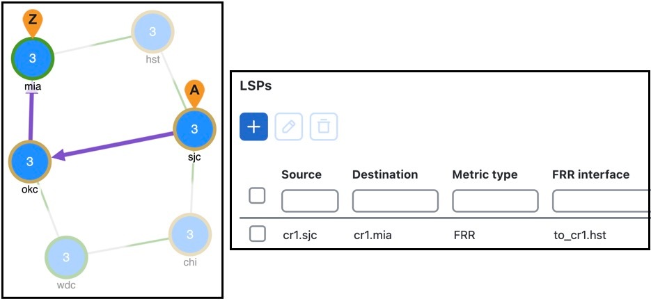
An unused FRR LSP path highlights in purple when it is selected from the LSPs table. When routed under failure, FRR LSPs appear as a dotted line.


FRR LSP routing

The source and destination of an FRR LSP can be any pair of nodes, although in practice the source and destination nodes are usually one hop (link protection) or two hops (node protection) apart. The source node for the FRR LSP has a designated interface that is configured so that it is avoided during Fast Reroute simulations. This is the protected interface.

This is configured using the FRR interface property, which is set in the Edit LSP page when manually creating the FRR LSP, or it is automatically created when running the FRR LSPs initializer. The initializer derives it from interface's FRR enabled property.

Example

This image shows an FRR LSP sourced at sjc, destined for mia, and whose protected interface (FRR interface) is to_cr1.hst. Therefore, the FRR LSP path routes towards okc and away from hst. If this FRR interface property were to_cr1.okc instead, the FRR LSP path would route sjc-hst-mia, away from okc.

Figure 1. FRR LSP routing example

Like other LSPs, FRR LSPs can use actual and named paths. Unlike other LSPs, they do not use setup bandwidth when routing and they only use one LSP path.


Types of FRR LSP protection


Configure routing around failures

When one or more failures occur, these decisions determine which FRR LSP to take:

Before you begin

  • LSPs must be configured to be protected by FRR LSPs. For information about setting up FRR LSPs, refer to Set up fast reroute simulations.

  • Any interfaces along the FRR LSP path must be configured to be protected by FRR LSPs. For information about protecting interfaces, refer to Mark LSPs for protection or the FRR LSPs initializer (which automates the process of setting these).

Procedure

1.

For each such interface on the LSP path, Cisco Crosswork Planning checks for an FRR LSP protecting that interface whose destination is a node further down the path of the LSP.

2.

If more than one of these FRR LSPs exist, Cisco Crosswork Planning chooses the one that is farthest down that path of the protected LSP, thus simulating standard FRR behavior that prefers node protection over link protection.

If more than one eligible FRR LSP has the same destination farthest down the protected LSP path, the FRR LSP is chosen arbitrarily among them.

3.

If more failed circuits or nodes occur after this destination, further FRR LSPs are chosen in the same manner.


Set up fast reroute simulations

Use this task to set up FRR simulations by configuring protection properties, SRLGs, FRR LSP initialization, and simulation execution.

Procedure

1.

Set appropriate properties on LSPs to mark them for protection. Refer to Mark LSPs for protection.

2.

If protecting SRLGs, associate a node with the SRLG in order to establish the protected interface within it. Refer to Identify SRLGs for protection.

3.

If you are using the initializer to create FRR LSPs, identify which interfaces to protect. Refer to FRR LSPs initializer.

4.

Create the FRR LSPs using the FRR LSPs initializer or manually. Refer to FRR LSPs initializer or Create FRR LSPs manually.


Mark LSPs for protection

Use this task to mark LSPs for FRR protection by setting properties that identify protected interfaces, nodes, or SRLG resources.

Procedure

1.

Select the required LSPs from the LSPs table and click Edit icon.

2.

In the LSPs details section, check the FRR enabled check box.

This appears as "true" in the FRR enabled column of the LSPs table. If this is "false", the LSP is not protected.
3.

In the Routing section, set the Routing type as Autoroute or FA (Forwarding Adjacency).

The type appears as "autoroute” or “FA” in the Metric type column of the LSPs table.


Identify SRLGs for protection

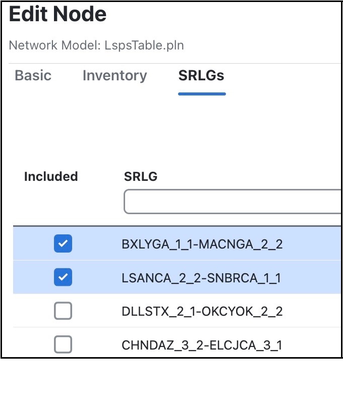
To simulate a router’s “exclude protect” configuration, associate the source node of the protected circuit with the SRLG. If that circuit fails, the FRR LSP reroutes around all circuits within that SRLG.

Procedure

1.

Select the source node of a circuit within an SRLG that you want to protect. Click Edit icon or choose > Edit.

2.

Click the SRLGs tab.

3.

Choose one or more SRLGs with which you want to associate this node.

4.

Save your changes.


FRR LSPs initializer

The FRR LSPs initializer automatically creates link-protection or node-protection FRR LSPs when these conditions are met:

  • One or more LSPs have their FRR enabled property set (refer to Mark LSPs for protection).

  • One or more interfaces on the path of these LSPs have their FRR enabled property set. This tells the FRR LSPs initializer how to create the FRR LSPs so that in the event of a failure, the interface would be avoided when the LSP is being rerouted.

    • This property is set in the MPLS tab of the Edit Interface window. The FRR enabled column in the Interfaces table shows "true" if the interface is included or "false" if it is not.

    • After FRR LSPs are created, the interface is listed in the FRR interface column in the LSPs table.

The initializer creates the FRR LSPs based on these FRR enabled properties and based on whether you choose to create link or node protection.

  • Link protection: Cisco Crosswork Planning creates FRR LSPs for each pair of next-hop nodes (two connected nodes) in the protected LSP path where the egress interface of the first hop has its FRR enabled property set.

  • Node protection: Cisco Crosswork Planning creates FRR LSPs between each set of next next-hop nodes (three connected nodes) in the protected LSP path where the egress interface of the first hop has its FRR enabled property set.

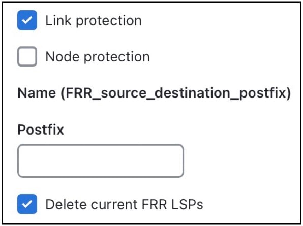
These new FRR LSPs are named FRR_<source> _<destination> _<postfix>, where postfix is optional and set in the initializer’s page.


Run the FRR LSPs initializer

Use this task to run the FRR LSPs initializer and create protection LSPs for eligible protected LSPs.

Procedure

1.

Open the plan file (refer to Open plan files). It opens in the Network Design page.

2.

From the toolbar, choose Actions > Initializers > FRR LSPs.

3.

Select the nodes you want to optimize. If you do not choose any nodes, the initializer uses all nodes in the plan file. Click Next.

4.

Choose whether to create FRR LSPs that protect links (circuits), nodes, or both.

FRR LSPs initializer options
5.

(Optional) Enter a postfix to add to the end of the names of the newly created FRR LSPs.

6.

(Optional) Uncheck the Delete current FRR LSPs check box to retain the existing FRR LSPs.

7.

Submit your changes.


Create FRR LSPs manually

Use this task to create FRR LSPs manually and set the properties required for link or node protection.

This section describes the required properties for an FRR LSP. It does not describe all the options available when creating an LSP.

Procedure

1.

Open the plan file (refer to Open plan files). It opens in the Network Design page.

2.

Create an LSP using one of these options:

  • In the toolbar, choose Actions > Insert > LSPs > LSP.

  • In the Network Summary panel, click Add icon > LSPs in the LSPs page.

  • You can also choose an existing LSP to modify to be an FRR LSP. If doing so, click Edit icon or choose > Edit.

3.

Choose the source site and node of the FRR LSP.

4.

Choose the destination site and node, or enter a NetInt destination IP address. For information about NetInt destination IP addresses, refer to Unresolved LSP destinations and hops.

5.

In the Routing area, choose FRR as the Routing type.

6.

Specify the interface that is to be avoided during routing by choosing it from the FRR interface drop-down list or by entering its IP address in the NetInt FRRInterface field.

7.

Save your changes.


Run fast reroute simulation

FRR LSPs are routed only when simulating failures in the Fast Reroute simulation mode. Complete these steps to enable the Fast Reroute simulation mode.

Procedure

1.

Open the plan file (refer to Open plan files). It opens in the Network Design page.

2.

In the toolbar, click or choose Actions > Edit > Network options.

The Network options page opens.

3.

Click the Simulation tab.

4.

In the Simulation convergence mode section, choose Fast reroute from the Layer 3 drop-down list.

5.

Save your changes.