Cisco Crosswork Planning Design 7.2.x User Guide

PDF

Cisco Crosswork Planning Design 7.2.x User Guide

VPN model

Want to summarize with AI?

Log in

Describes the virtual private network (VPN) architecture and configuration framework used to establish secure, encrypted connections between remote sites or users and the corporate network over public internet infrastructure.


A VPN model is a representation of a virtual subnetwork within the overall network architecture. Viewing and simulating VPN within Cisco Crosswork Planning helps with many network tasks and answers these questions:

  • Which VPNs are on my network? Where and how are they configured?

  • Which VPNs are using congested interfaces?

  • Which VPNs will experience congestion under any of a given list of failure scenarios?

  • Which failure scenarios cause the worst-case congestion or latency for a VPN?

There are many varieties of VPNs. For example, there are Layer 2 (L2) VPNs and Layer 3 (L3) VPNs, each with different categories within it, as well as vendor-specific VPN implementations. Each VPN type has its own specific configuration and terminology. The Cisco Crosswork Planning VPN model supports a number of these VPN types based on either route-target or full-mesh connectivity.

VPN objects

This section lists the VPN objects and their descriptions with examples for both Layer 2 and Layer 3 VPN configurations.

Object

Description

Examples

VPNs

A set of VPN nodes that can exchange data with each other.

  • Layer 2 VPN: The VPN represents an individual VPLS containing Virtual Switch Interfaces (VSIs).

  • Layer 3 VPN: The VPN represents sets of VRFs associated with a set of VPN nodes that forward traffic between themselves. This set of VRFs signifies a single customer or service.

VPN nodes

Connection points in a VPN. They exist on standard nodes, and each node can contain multiple VPN nodes. A VPN node can be in only one VPN.

  • Layer 2 VPN: The VPN node represents the VSIs configured on each router.

  • Layer 3 VPN: The VPN node represents the VRF instances configured on each router.


VPN topology and connectivity

VPN topology and connectivity is a network configuration that

  • are established through Route Targets (RTs) or through a full mesh of VPN nodes

  • enables Cisco Crosswork Planning to calculate which demands between VPN nodes carry traffic for a particular VPN, and

  • allows calculation of VPN vulnerability to certain failure and congestion scenarios.

A demand is associated with a VPN, meaning it carries traffic for that VPN, if these conditions are true:

  • Two VPN nodes are in the same VPN.

  • Demand is in the same service class as the VPN.

  • Only for VPNs with RT connectivity, the RT export property of one VPN node must match the RT import property of another VPN node.

After demands are associated with the VPN, this configuration simulates the associated access circuits exchanging traffic as if they were on the same LAN. Note that a demand associated with a VPN can additionally contain other traffic that is for that VPN.

VPN connectivity types

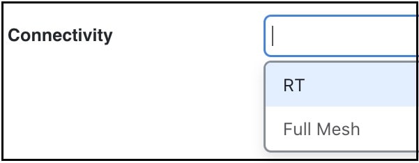
The Connectivity property is set in the Add/Edit VPN page.

VPN connectivity options

This table compares connectivity types and their characteristics.

Connectivity

Description

RT

Route targets model the more complex connectivity used in Layer 3 VPNs, such as hub-and-spoke networks. Here, the VRFs exchange data with one another based on the matching of RT export and RT import properties set for each VPN node. However, having an import/export pair does not create bidirectional communication. Instead, traffic flows in the opposite direction of the routed advertisements.

For example, if node A’s RT import matches node B’s RT export, traffic can flow from node A to B. For traffic to flow from node B back to node A, node B must have an RT import that matches an RT export of node A. This combination of matching imported and exported RTs defines which VPN nodes can exchange data. The VPN name identifies the VPN itself.

Full Mesh

Full mesh connectivity refers to a complete mesh of connections between VPN nodes in a VPN where they can all communicate with each other. This connectivity is typical in a VPLS, where all VSIs identify one another based on a common AGI.