Cisco Crosswork Planning Design 7.2.x User Guide

PDF

Cisco Crosswork Planning Design 7.2.x User Guide

Dynamic LSP routing and CSPF

Want to summarize with AI?

Log in

Explains how dynamic RSVP LSP routing uses CSPF, describes related MPLS interface properties, LSP reservation views, and setup bandwidth initialization.


If an RSVP LSP contains no LSP paths (also called MPLS TE tunnel paths), it is routed dynamically using Constrained Shortest Path First (CSPF). The weights used for the CSPF calculation are the TE metrics per interface. If the TE metric is not configured for an interface, then IGP metric is used.

If there are equal-cost routes, CSPF uses these selection criteria in order:

  • Bandwidth available: The route with the greatest reservable bandwidth is chosen.

  • Hop count: If bandwidth is equal, the route with the fewest hops is chosen.

  • Random: If neither bandwidth nor hop count differentiate the routes, a route is chosen at random.

CSPF properties are set in the Edit LSP page and are viewable from the LSPs table. Note that these properties are available only for RSVP LSPs.
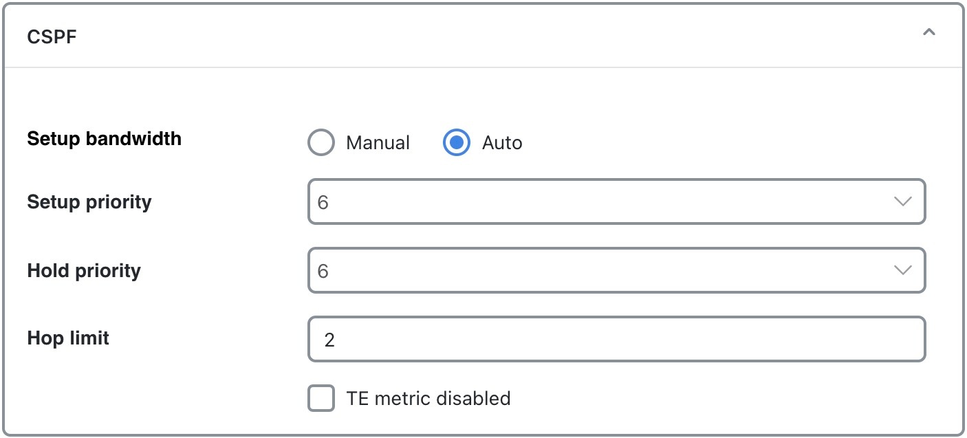
CSPF options
  • Setup bandwidth (Manual): The amount of traffic (in Mbps) the source node requests for this LSP. The requested bandwidth is available from the reservable bandwidth of each interface in the path.

  • Setup bandwidth (Auto): Automatically updates the Setup BW Sim value when using the Auto bandwidth convergence mode.

  • Setup priority: Sets the priority for allocating reservable bandwidth. This is the order in which LSPs are signaled. The lower the number, the higher the priority.

  • Hold priority: Determines which LSPs can preempt others on the shortest path. This is typically set for a particular service or traffic type. The lower the number, the higher the priority.

  • Hop limit: Specifies the maximum number of hops permitted in the LSP route. If no path is available with this number of hops or fewer, the LSP is not routed.

  • TE metric disabled: Uses IGP metrics for the LSP route if checked. If unchecked (default), the LSP uses TE metrics.


Configure interface MPLS properties

Use this task to update the MPLS properties on one or more interfaces or circuits to control reserved bandwidth, traffic engineering metrics, and LSP routing behavior.
MPLS properties are set in the MPLS tab of the Edit interface or circuit page, and are viewable in the Interfaces or Circuits table.

Procedure

1.

Open the plan file (refer to Open plan files). It opens in the Network Design page.

2.

Select one or more interfaces or circuits from their respective tables.

3.

Click Edit icon.

Note

If you are editing a single interface or circuit, you can also use the > Edit option.

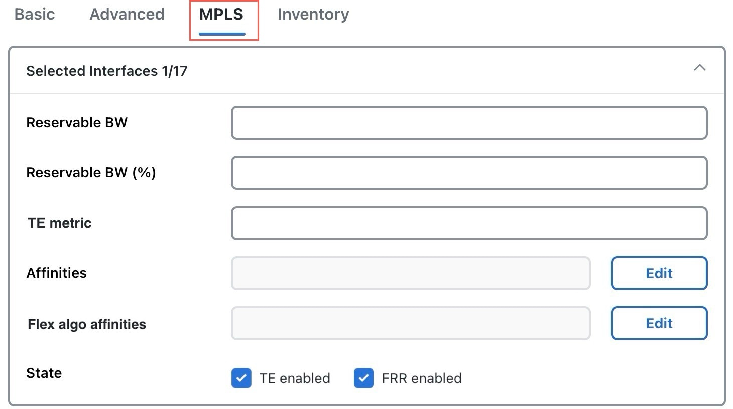
Figure 1. Interface MPLS properties
Interface MPLS properties
4.

Set these properties:

  • Reservable BW: Shows the amount of bandwidth that can be reserved by LSPs routed over the interface.

  • Reservable BW (%): Shows the percentage of bandwidth that can be reserved by LSPs routed over the interface.

  • TE metric: Determines which path an LSP takes.

  • Affinities: Lists which affinities are set. For more information, refer to Affinities.

  • Flex algo affinities: Lists the FlexAlgo affinities assigned to the interface (MPLS).

  • State:

    • TE enabled: Identifies whether an LSP can be routed over the interface. If checked, the value is set to True, and TE metrics are used in routing the LSP, provided the LSP’s TE metric disabled field is unchecked.

    • FRR enabled: Designated interface to be avoided by the FRR LSP. Only interfaces with this property set are used by the FRR LSPs initializer when creating FRR LSPs. This property does not affect FRR LSPs that are manually created. For more information, refer to Fast Reroute (FRR) simulations.

5.

Save your changes.

These columns are updated in the Interfaces or Circuits tables:

  • TE metric sim: Derived column that shows the effective TE metric. If the TE Metric is empty, this is set to the IGP metric.

  • Resv BW sim: Derived column.

    • If a Reservable BW value is entered, this is copied to the Resv BW sim column.

    • If Reservable BW and Reservable BW (%) are “na”, the Resv BW sim is copied from the Capacity sim column.

    • If Reservable BW is “na”, but Reservable BW (%) has a value, the Resv BW sim value is derived by this formula:

      Capacity sim * (Reservable BW (%) / 100)

      If needed, you can change this behavior so that reserved bandwidth constraints are not used during simulations, which could be useful for planning purposes. For information, refer to Ignore reservable bandwidths for capacity planning.

  • To determine how much of the interface traffic is contained in LSPs, show these columns in the Interfaces table. The total of the two equals Traff sim.

    • Traff sim LSP: The total amount of LSP traffic on the interface.

    • Traff sim non LSP: The total amount of non-LSP traffic on the interface.

    To determine which interfaces carry LSP traffic, sort the columns. To determine the demands associated with one or more selected interfaces based on whether or not they have LSP traffic, select them and choose > Filter to demands > Through all interfaces. Then, choose > Filter to LSPs.

  • Loadshare: Show this column in the LSPs table. It indicates the value for redistributing either traffic across LSPs based on the ratio of this value with other LSPs that are parallel (have the same source and destination).


View LSP reservations

Use this task to view LSP reservations on interfaces and compare reservation utilization with simulated traffic in the network plot.

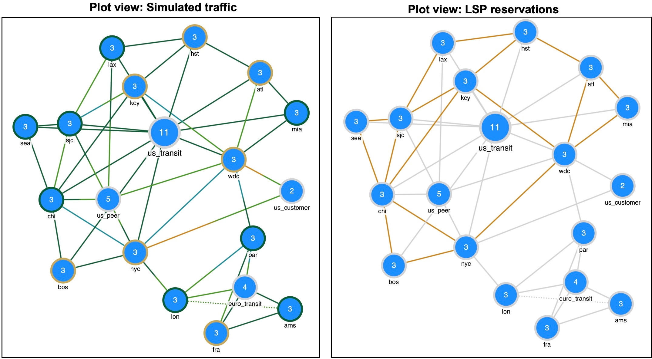
In the LSP reservations mode, interfaces are colored according to the percentage of bandwidth (in comparison to what is reserved for the LSP).

Procedure

1.

Open the plan file (refer to Open plan files). It opens in the Network Design page.

2.

From the Plot view drop-down list in the toolbar, choose LSP reservations.

The network plot updates, displaying interfaces color-coded by the percentage of bandwidth reserved for LSPs. The utilization colors are based on the LSP util column in the Interfaces table. LSP util is the sum of all setup bandwidths for all LSPs through the interface, as a percentage of the Resv BW sim.

Simulated traffic versus LSP reservations shows how the network plot changes based on the Plot view options you select, such as Simulated traffic or LSP reservations.

Figure 2. Simulated traffic versus LSP reservations
LSP reservations views

Calculate LSP setup bandwidth

Use this task to calculate setup bandwidth values for selected RSVP-TE LSPs by running the LSP setup bandwidth initializer.

The LSP setup bandwidth initializer calculates the setup bandwidth for existing RSVP-TE LSPs. The setup bandwidth is set to the maximum amount of demand traffic passing through the LSP for the traffic levels selected.

If using only one traffic level, the best practice is to use the Autobandwidth convergence mode ( > Simulation > Simulation convergence mode). For more information, refer to Autobandwidth-enabled LSPs.

Procedure

1.

Open the plan file (refer to Open plan files). It opens in the Network Design page.

2.

From the toolbar, choose Actions > Initializers > LSP setup bandwidth.

LSP setup bandwidth initializer options
3.

Select the LSPs you want to optimize.

4.

Choose whether to set the setup bandwidth value to be equal to the maximum amount of traffic passing through each tunnel across selected traffic levels. Use the Initialize setup bandwidth from traffic levels check box for this purpose.

5.

Choose which traffic levels to use for demand traffic.

6.

Choose whether to set the load share values to be equal to the setup bandwidth. To set, check the Initialize loadshare from setup bandwidth check box.

7.

Submit your changes.