Describes the traffic engineering requirements and routing policies that define how data flows should be distributed between different Autonomous Systems to meet performance, capacity, and business objectives.
Route selection between internal ASes
Demands routed within a single AS have a specified source node and destination node where traffic originates and terminates. Demands routed between two connecting internal ASes are specified in the same manner: with a source node in the first AS and a destination node in the second.
Routing policy configuration
Cisco Crosswork Planning routes within an AS, to and from the border exit point, are determined by the IGP protocols. The selection of border exit point is modeled by the Routing policy, which is set to either Shortest Exit or Respect MEDs. This property is set in the Edit AS Relationships page, which is accessed through the Edit AS page.
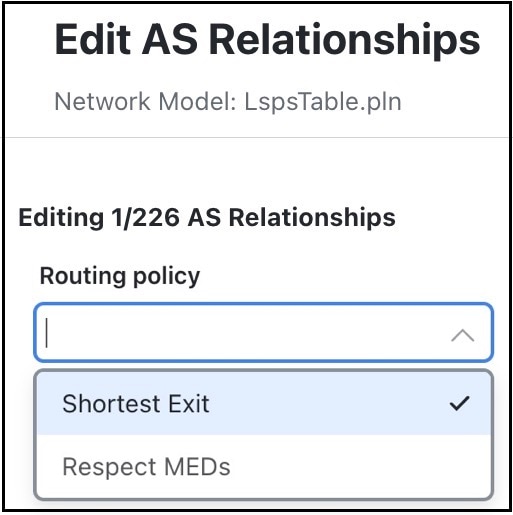
The routing policy options include:
-
Shortest Exit: The border exit node is selected, which is closest to the source node, within the IGP of the source AS. If there is a tie, the exit node with the lowest BGP ID is used.
-
Respect MEDs: The border exit node is selected, which is closest to the destination node, within the IGP of the destination AS. If there is a tie, the exit node with the lowest BGP ID is chosen.
Routes between external and internal ASes
This topic lists typical routing configurations that can be constructed by applying different combinations of routing policies for traffic in both directions between two ASes.
Typical AS routing configurations
Different AS relationship types use specific routing policy combinations:
-
In a peer relationship, routing in both directions is Shortest Exit, which means each controls its own border exit points.
-
For a customer relationship, the customer determines the border exit points for traffic in both directions.
-
For a transit relationship, the transit AS provides paid transit to the internal AS, so the internal AS determines all border exit points.
|
Type |
Policy to |
Policy from |
|---|---|---|
|
Peer |
Shortest Exit |
Shortest Exit |
|
Customer |
Respect MEDs |
Shortest Exit |
|
Transit |
Shortest Exit |
Respect MEDs |
Like traffic routed within an AS, traffic routed between ASes is represented by demands. However, for demands from and/or to external ASes, the external AS is defined AS the source or destination of the demand. Optionally, the specific node in the external AS from which the traffic enters or exits the internal AS is also specified.
Failover between nodes in the external AS can be modeled. For example, if the traffic is sourced from an external AS and if the peering circuit from which traffic is entering the internal AS under normal operation fails, the traffic can enter the internal AS from a different interface or peering node in the same external AS. In the Demands table, the sources and destinations are represented as:
AS{<ASN>}:if{node_name|interface_name}
Example: AS{33287}:if{cr01.newyork.ny|POS3/7/0/0}
The AS that controls the routing chooses which peering node to use. If the internal AS controls the routing, then because the topology of the internal AS is known, you can simulate the routing to the peering node. However, because Cisco Crosswork Planning has limited knowledge of the external AS topology, if the external AS controls the routing, you cannot predict how traffic will be distributed among the exit points.
Determine the AS that controls the routing
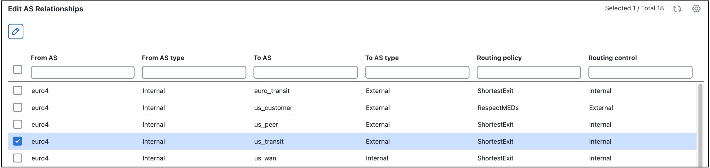
The AS that controls the routing is determined by the AS type, direction of the demand, and the Routing policy property AS described in this table.
|
Direction |
Routing Policy |
AS with Routing Control |
|---|---|---|
|
External AS to Internal AS (Ingress) |
Respect MEDs |
Internal |
|
Shortest Exit |
External |
|
|
Internal AS to External AS (Egress) |
Respect MEDs |
External |
|
Shortest Exit |
Internal |
Effects of routing policy and routing control
Two ASes can be in one of four different routing relationships to one another, depending on which of the two routing policies is chosen in each direction. Traffic routing behavior depends on which AS has control:
-
If traffic is routed to an external AS when it has control and there is no knowledge of its topology, a set of demands is created from the source in the internal AS (or from another external AS), each with a destination set to one of the border nodes in the external AS. This way, any division of traffic between the exit points can be modeled.
-
If traffic is routed to an external AS when an internal AS has control, a single demand is created from the source to the AS itself. Cisco Crosswork Planning simulations determine the correct exit point for this single demand based on the source.
-
If traffic is to be routed from an external AS when it has control, a demand is created from each node in the external AS to each node in the internal AS.
-
If traffic is to be routed from an external AS when an internal AS has control, a demand is created to each node in the internal AS using the external AS AS the source. The demand originates from one or multiple nodes in the external AS, depending on the topology and the metric cost to reach the destination node. For example, a single demand from an external AS to a specific node could be sourced from two different nodes in the external AS, each carrying 50% of the demand traffic.
|
Direction |
Routing Policy |
AS with Routing Control |
Demand Source or Destination Endpoint in Remote AS |
Number of Demands |
|---|---|---|---|---|
|
External AS to Internal AS (Ingress) |
Respect MEDs |
Internal |
Entire external AS |
One only |
|
Shortest Exit |
External |
Border nodes |
One for each node |
|
|
Internal AS to External AS (Egress) |
Respect MEDs |
External |
Border nodes |
One for each node |
|
Shortest Exit |
Internal |
Entire external AS |
One only |
External meshes
An external mesh is a network configuration that
-
consists of two or more external ASes with a Type property of external, and
-
enables or restricts the advertisement of BGP routes between external ASes.
External mesh property configuration
An internal AS typically restricts advertisement of BGP routes for some external ASes to other external ASes. For example, destinations reachable through the transit network would not be advertised to a peer, or vice versa. In Cisco Crosswork Planning, these restrictions are represented by the absence of demands between the two external ASes.
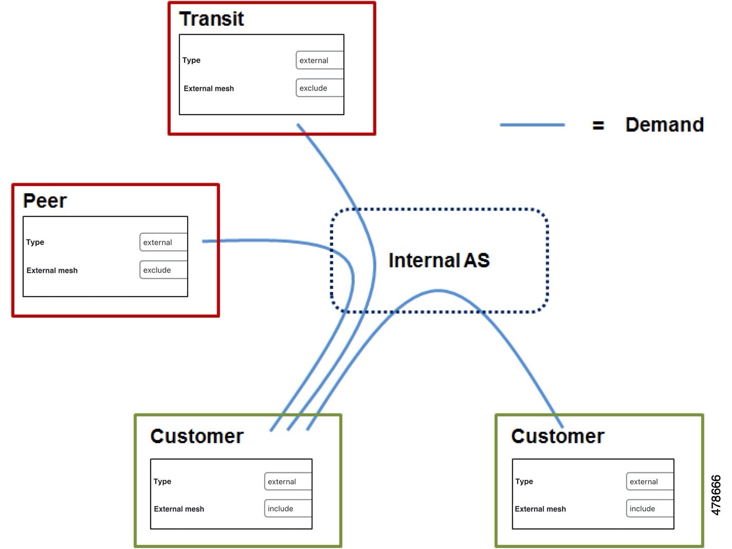
Each AS has a property called External mesh, which Cisco Crosswork Planning uses when inserting demand meshes into a plan. Demands are created for external ASes only if one or both ASes have External mesh set to include. If both ASes are set to exclude, no demands are created for the external AS. For example, in Figure 1 the peer and transit ASes are both set to Exclude, so no demands are created between those ASes. All other external AS demands are included in the demand mesh. Table 1 shows the External Mesh settings for common AS relationships.
This table shows the External Mesh settings for common AS relationships.
|
Relationship |
External Mesh Setting |
Result |
|---|---|---|
|
Peer |
Exclude |
Demands permitted to/from customers only |
|
Customer |
Include |
Demands permitted to/from all external ASes |
|
Transit |
Exclude |
Demands permitted to/from customers only |
For internal ASes, the External mesh property is ignored. More complex route advertisement policies cannot be represented by these simple External mesh settings. In this case, demand mesh creation must be performed in several steps, possibly using a script.