Cisco Crosswork Planning Design 7.2.x User Guide

PDF

Cisco Crosswork Planning Design 7.2.x User Guide

SR-TE optimization

Want to summarize with AI?

Log in

Explains how SR-TE optimizations enable advanced traffic engineering, flexible path calculation, and network reliability for modern IP and MPLS infrastructures.


You can use the SR-TE optimization tool (Actions > Tools > SR LSP optimization > SR-TE optimization to design, capacity plan, and manually configure networks to meet the objectives. This tool supports both Inter-Area and Inter-AS functionalities.

This tool helps you design networks for objectives such as:

  • TE Metric or Delay Minimization: Minimize distance between hops with respect to metrics other than IGP metrics. These can be either TE metrics configured on interfaces (which can be set proportional to circuit latency) or latencies (delays) for each circuit. An example application is a differentiated service in which latency-sensitive network traffic is routed on shortest latency paths, while the bulk of the traffic routes over cost-optimized paths.

  • Avoidance: Create or optimize segment lists so they avoid routing through specified objects (nodes, interfaces, or SRLGs). An example application is routing pairs of LSPs, each over a different plane in a dual-plane network. The same traffic is routed over both LSPs simultaneously, thus improving availability.

    While there is an option to specify a maximum number of hops, doing so might not achieve the lowest possible latency. In this case, the best achievable solution is provided.

    You can additionally avoid unnecessary LSP churn by specifying boundaries (bounds) on the path length and margins within which the shortest path must be optimized.

    Note
    Unless qualified with “TE” or “IGP,” the term metric in this chapter applies to IGP metric, TE metric, or delay.
SR-TE optimization input properties


Path metric optimization options

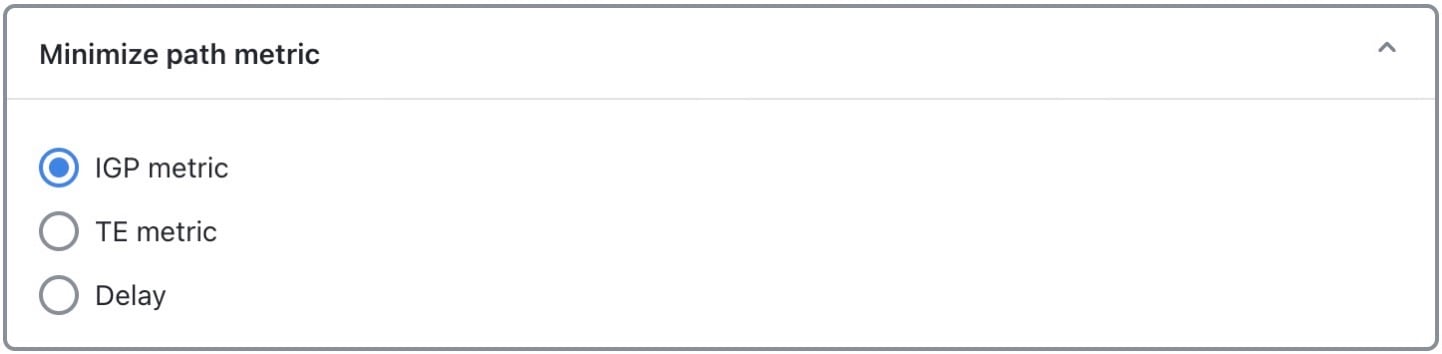
The Minimize path metric section defines whether to optimize SR LSPs based on interface IGP metrics, interface TE metrics, or circuit delays. This minimization is for the sum of the metrics along the path. These properties are configurable from the Edit Interface page, and delays can also be set in the Edit Circuit page.

Note
For inter-AS SR LSPs, these metrics are calculated end-to-end for the LSP, not per AS.
Figure 1. Minimize path metric options
Minimize path metric options

Bound and margin options

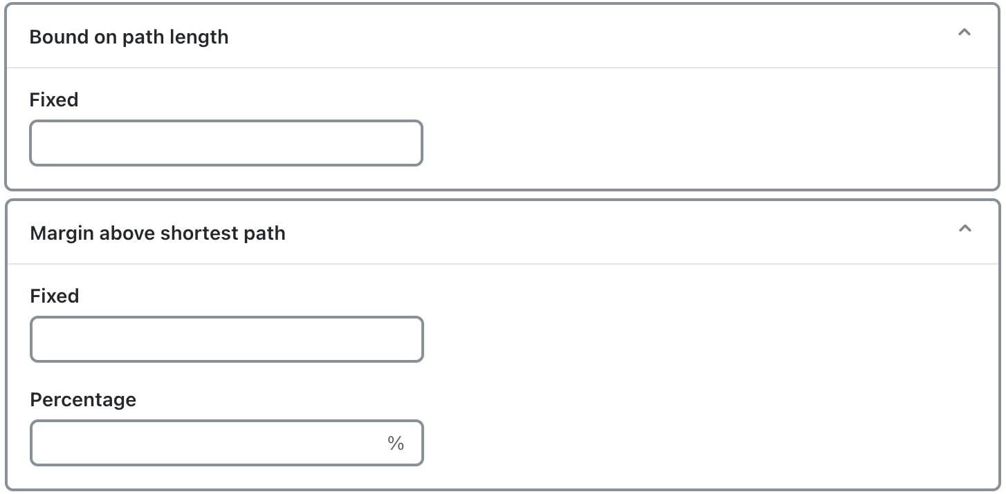
Bounds and margins identify which paths to optimize, as well as when to stop optimizing a given path. If you enter a value for more than one restriction, Cisco Crosswork Planning uses the strictest limitation as the optimization target. If there is no bound or margin specified, the system optimizes LSP paths to the best possible solution (lowest total metrics for the LSP path).
Figure 2. Bound and Margin panels
Bound and Margin options

Bound: Maximum acceptable path length

The Fixed Bound entry in the Bound on path length section lets you set the maximum path metric that is acceptable. Cisco Crosswork Planning tries to optimize LSP paths with metrics that exceed this bound. If a solution adhering to this bound cannot be found, the best possible solution is provided and bound violations are listed in the report. LSP paths that are less than or equal to this bound are not optimized.

Example: If you select to optimize LSP paths based on TE metrics, the value entered is 50, and the sum of TE metrics on the LSP path is 51, that LSP path is optimized.

Enter a number based on the selected path metric. A TE metric is a property values whose total sum for the LSP path cannot be exceeded. The delay is also a property value, but it is in milliseconds (ms). If you enter “50” and you have selected delay as the metric to optimize, this represents 50 ms as the maximum acceptable delay for the LSP path.

Margin: Maximum acceptable metric above shortest path

The Margin entries let you identify the acceptable deviation above the shortest achievable path metric. Any existing LSP path with a metric that is less than or equal to the shortest path metric plus the margin is not optimized.

  • Fixed: The amount by which a metric must be surpassed before it is optimized.

    Example: If an SR LSP route has a delay of 110, a fixed margin set to 10, and the shortest achievable delay path is 100, the current SR LSP is within the margin and will not be updated. If the fixed margin is set to 9, the SR LSP would be optimized.

    100 (shortest path) + 10 (fixed margin) = 110, so all paths greater than 110 are optimized.

  • Percentage: The amount by which a metric must be surpassed, expressed as a percentage of the shortest path, before it is optimized.

    • Example 1: If an existing SR LSP route has a TE metric of 210, a percentage margin set to 10%, and the shortest achievable TE metric path is 200, the current SR LSP is within the margin and will not be updated. If the current SR LSP had a metric of 225, it would be optimized.

      200 (shortest path) x .10 (percentage margin) = 20, so all paths greater than 220 must be optimized

    • Example 2: If an SR LSP route has a delay of 110, a fixed bound is set to 120, a fixed margin is set to 15, a percentage margin is set to 5%, and the shortest achievable delay path is 100, the strictest of these restrictions takes precedence, and the SR LSP is optimized.

      Fixed Bound = 120

      100 (shortest path) + 15 (fixed margin) = 115

      100 (shortest path) x .05 (percentage margin) = 5, so all paths greater than 105 are optimized because it is the strictest margin.


Optimization constraints

These constraints specify restrictions for the optimizations:

  • Maximum segment list hops per SR LSP: The maximum number of segment list hops that any given segment list can contain after optimization. If no value is specified, Cisco Crosswork Planning creates as many hops as needed to optimize the SR LSP.

  • Avoid: Do not permit optimized segment lists to route through the selected objects (nodes, interfaces, or SRLGs). This constraint is useful when modeling dual-plane topologies that route disjoint LSPs.

  • Restrict segment node to core nodes: Segment list node hops must be core nodes (nodes that have their Function property set to “core”), and the local node of segment list interface hops must be a core node. An SR LSP could still route using edge nodes if they are not used as hops.


Run SR-TE optimization

Complete these steps to perform SR-TE optimization.

Procedure

1.

Open the plan file (refer to Open plan files). It opens in the Network Design page.

2.

From the toolbar, choose any of these options:

From the toolbar, choose Actions > Tools > SR LSP optimization > SR-TE optimization.

Alternatively, choose Preset workflows > Perform optimization, select SR LSP Optimization as the optimization type, select SR-TE optimization from the drop-down list, and click Launch.

3.

Choose the LSPs you want the optimizer to consider and click Next.

4.

Specify these parameters:

  1. In the Minimize path metric section, choose whether to optimize SR LSPs based on interface IGP metrics, interface TE metrics, or circuit delays. For more information, refer to Path metric optimization options.

  2. In the Bound on path length and Margin above shortest path sections, specify the values as per your requirement. For more information, refer to Bound and margin options.

  3. In the Constraints section, specify any restrictions for optimization. For more information, refer to Optimization constraints.

5.

(Optional) In the Tag updated LSPs with field, override the defaults for how LSPs are tagged (SROpt).

6.

On the Run Settings page, choose whether to execute the task now or schedule it for a later time. Choose one of these Execute options:

  • Now: Choose this option to execute the job immediately. The tool runs and changes are applied to the network model immediately. A summary report appears. You can access the report any time later using Actions > Reports > Generated reports option.

  • As a scheduled job: Choose this option to execute the task as an asynchronous job. Set these options:

    • Priority: Select the priority of the task.

    • Engine profiles: Select the engine profile as needed. This section lists all the available asynchronous engine profiles.

    • Schedule: Set the time at which you want to run the tool.

    The tool runs at the scheduled time using the selected engine profile. You can track the status of the job at any time using the Job Manager page (from the main menu, choose Job Manager). Once the job completes, import the output plan file into user space to visualize it. For more information, refer to Access output plan files from job manager.

    Note
    Ensure that you save the plan file before you schedule the job. Any unsaved changes in the plan file are not considered when you run the tool as a scheduled job.
7.

(Optional) If you want to display the result in a new plan file, specify a name for the new plan file in the Display results section.

In the previous step:
  • If you have selected to run the task immediately, by default, the changes are applied on the current plan file. If you want to display the results in a new file, select the Display results in a new plan file check box and enter the name of the new plan file.

  • If you have scheduled the task to run at a later time, by default, the results are displayed in the Plan-file-1. Update the name, if required.

8.

Submit your changes.

What to do next

Upon completion, a report is generated containing the results of the optimization, as well as verifications that the results met the criteria for avoiding nodes and meeting the specified bounds. To view this information, choose Actions > Reports > Generated report and click the Segment Route TE Optimization report link in the right panel.