Explains how to route demands through intra-area, inter-area, and specific LSPs, including demand routing order, explicit versus dynamic inter-area routing, creating private demands and LSPs, deleting demands, and configuring load sharing.
Routing through intra-area LSPs
Intra-area LSPs are modeled as IGP shortcuts. That is, the source of the demand using the LSP can be a node other than the ingress node into the IGP, and the destination node of the LSP can be a node other than the egress node from the IGP. A demand through intra-area LSPs does not require the LSP to traverse the full demand path.
Each intra-area LSP has a metric that helps determine which traffic is routed through the LSP. By default, autoroute LSPs have a metric equal to the shortest IGP distance from the source to the destination. However, you can configure static metrics for these LSPs that override this default. Static metrics can also be defined as relative to the shortest IGP distance, but these relative metrics are not currently supported in Cisco Crosswork Planning.
Configuration options
Forwarding adjacency (FA) LSPs always have a metric. If not specified, the default is 10. Forwarding adjacency LSP metrics are injected into the IGP so that nodes other than the source node of the LSP are aware of the path length through the forwarding adjacency LSP, and use it in their shortest path calculations.
To edit Autoroute and Forwarding adjacency settings, choose one or more LSPs from the LSP table, click  to open the Edit page, and edit the values in the Routing section.
Routing demands through inter-area LSPs
Since it is not possible to define metrics distances across ISP areas, there can be no well-defined metric for inter-area LSPs. Therefore, in Cisco Crosswork Planning, a demand only routes through an inter-area LSP if the demand’s endpoints are nodes matching the source and destination of the LSP, interfaces on these nodes, or external ASes whose ingress and egress points through the IGP are these nodes. This requirement is true regardless of the network option settings.
Routing inter-area LSPs
In Cisco Crosswork Planning, all nodes in a single AS are assumed to belong to a single IGP. If the plan file contains more than one AS, all IGPs defined in these ASes are of the same type. For information on how nodes are assigned to areas or levels, refer to Simulate Traffic Flow from Source to Destination Using Demands.
An inter-area LSP is an LSP whose source node and destination node have no areas in common. If available, inter-area LSPs follow actual paths, regardless of whether doing so violates the required order of routing through areas. For example, if following an actual path, an inter-area can enter and leave an OSPF area 0 more than once.
To understand the protocols that determine routing order when setting up inter-area LSPs, refer to Order of routing through areas. Other factors that determine how the inter-area LSPs are routed include whether the LSP type is RSVP or SR, and whether you have selected to require explicit hops at ABRs. For more information, refer to Explicit and dynamic inter-area LSP routing.
Inter-area Fast Reroute LSPs and inter-area IGP shortcut LSPs are not supported. If the source and destination nodes of a Fast Route LSP are in different areas, the LSP is not routed.
To successfully route traffic, demands must also match the privacy requirements. Autoroute, Forwarding adjacency (FA) properties, and LSP metrics are ignored. For more information on privacy, refer to Routing demands through private LSPs.
Order of routing through areas
Regardless of the LSP type and whether explicit hops are required, inter-area LSPs route through the backbone areas, where “backbone” means area 0 for OSPF or the Level 2 area for IS-IS.
-
If there are three or more areas, backbone areas must be between the source and destination nodes. Typically, there are no more than three areas and therefore, the backbone area must be in the middle. For example, an OSPF inter-area LSP would route from area 1 to area 0 (backbone) and then to area 2.
-
If there are only two areas, there can only be one backbone area, and either the source or the destination node must be in the backbone area.
Explicit and dynamic inter-area LSP routing
An OSPF ABR is a node that belongs to both area 0 and other OSPF areas. An IS-IS ABR is a node that belongs to both the Level 2 area and another IS-IS level.
There are two modes of routing inter-area LSPs:
-
Explicit hop mode: Requires explicit hops to be set on ABR nodes. This approach simulates actual router behavior where ABR explicit hops are required.
-
Dynamic mode: Does not require explicit hops at ABR nodes and allows routing an LSP dynamically across multiple areas. Though this does not simulate actual router behavior, it is useful for planning inter-area LSP routes.
Configuration option
These modes are specified using the network option LSP routing requires ABR explicit hops in the Label Switched Paths section. If this option is selected, inter-area LSPs are routed based on explicit hops set on the ABR nodes.
-
An inter-area RSVP LSP must contain a named path, and the named path must contain explicit hops at ABRs for each required area crossing.
-
An inter-area SR LSP must contain a segment list, and the segment list must contain explicit node hops at ABRs for each required area crossing.
If this option is not selected, inter-area LSPs are routed dynamically and explicit hops at ABRs are not required. To leave one area and enter another, the inter-area LSP routes to the closest ABR in the current area that also borders the area it is entering.
Routing demands through private LSPs
A private LSP is a special LSP that
-
carries traffic dedicated to specific demands only
-
simulates the operation of MPLS Layer 2 VPNs, providing an exclusive route for the associated demands, and
-
interrupts all traffic associated with the LSP if it fails.
Configuration and identification
To configure LSPs that simulate Layer 2 VPNs, use one of these two methods:
-
Create dedicated demands for existing LSPs. The created demands will match the LSPs in source and destination. For more information, refer to Create private demands for existing LSPs.
-
Create private LSPs from existing demands. The created LSPs will match the existing demands in source and destination. For more information, refer to Create private LSPs for demands.
System indicators for private LSPs include:
-
LSPs table: The Private column is set to true.
-
Demands table columns: The Private LSP name and Private LSP source columns are set to true.
Create private demands for existing LSPs
Before you begin
Ensure that LSPs currently exist in the network model.
Procedure
-
From the toolbar, choose .
Alternatively, in the Network Summary panel on the right side, click
 > Demands for LSPs in the LSPs tab.
The LSPs tab may be available under the More tab. If it is not visible, then click the Show/hide tables icon (
 ) and check the LSPs check box.
Figure 1. Create demand for LSPs page 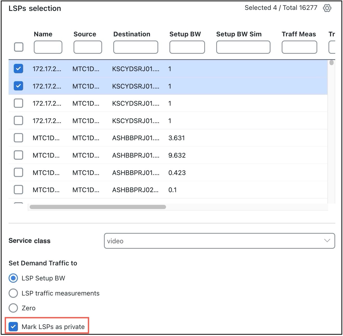
Create private LSPs for demands
Before you begin
Ensure that demands exist in the plan file.
Procedure
-
From the toolbar, choose .
Alternatively, in the Network Summary panel on the right side, click
> LSPs for demands in the LSPs tab.The LSPs tab may be available under the More tab. If it is not visible, then click the Show/hide tables icon (
) and check the LSPs check box.Figure 2. Demands selection page 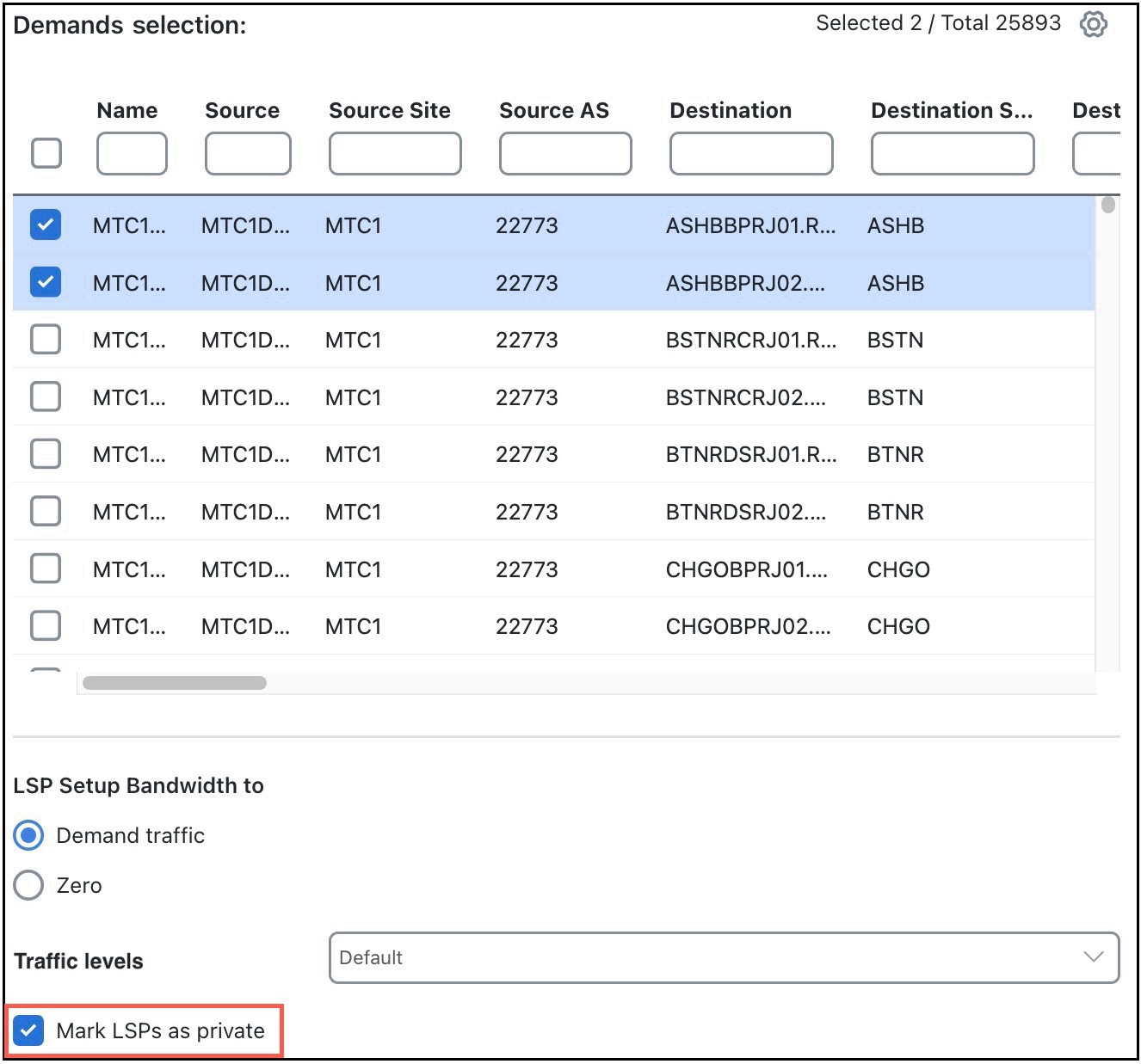
The newly created LSPs are highlighted in the LSPs table.
Configure automatic demand deletion for private LSPs
By default, when you delete a private LSP, the related demand remains in the system.
Procedure
-
In the toolbar, click
 or choose .
 The Network options page opens.
Load sharing between LSPs
Loadshare ratio examples
If two LSPs are parallel, and one has a Loadshare property of 2 and one has a Loadshare property of 1, there will be a 2:1 ratio of traffic shared between them. The top half of Figure 67: Examples of two parallel LSPs with equal loadsharing and 2:1 loadsharing shows an example of two parallel LSPs that are routed using strict explicit paths. Each has a Loadshare value of 1, which means the traffic is routed using a 1:1 loadshare ratio so that each LSP carries 50% of the traffic. In contrast, the lower half shows the same parallel LSPs with a 2:1 ratio. That is, one LSP has a Loadshare value of 2, and one has a Loadshare property value of 1. The LSP with a Loadshare value of 2 carries 66% of the traffic, while the other carries 33%.
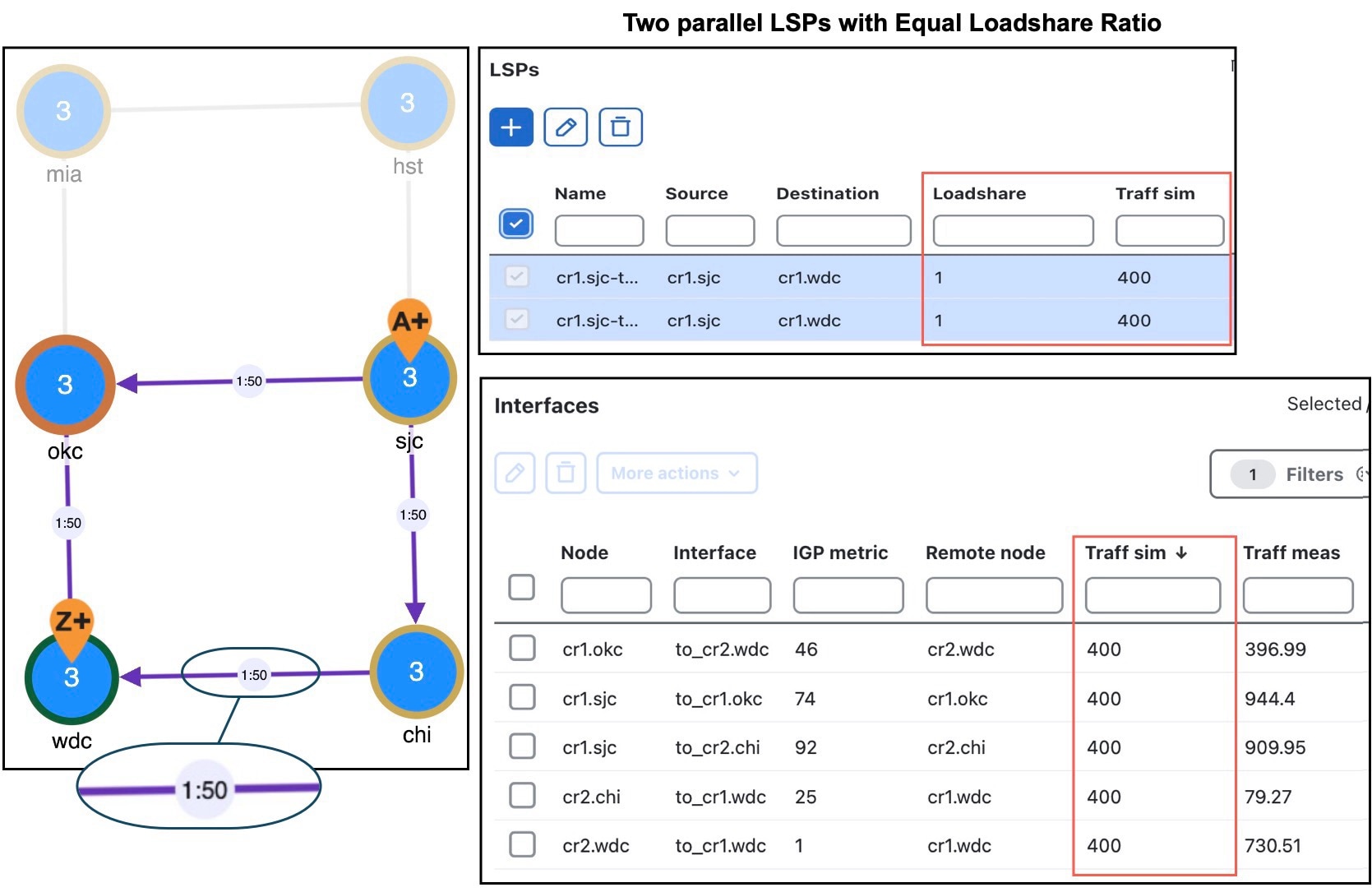
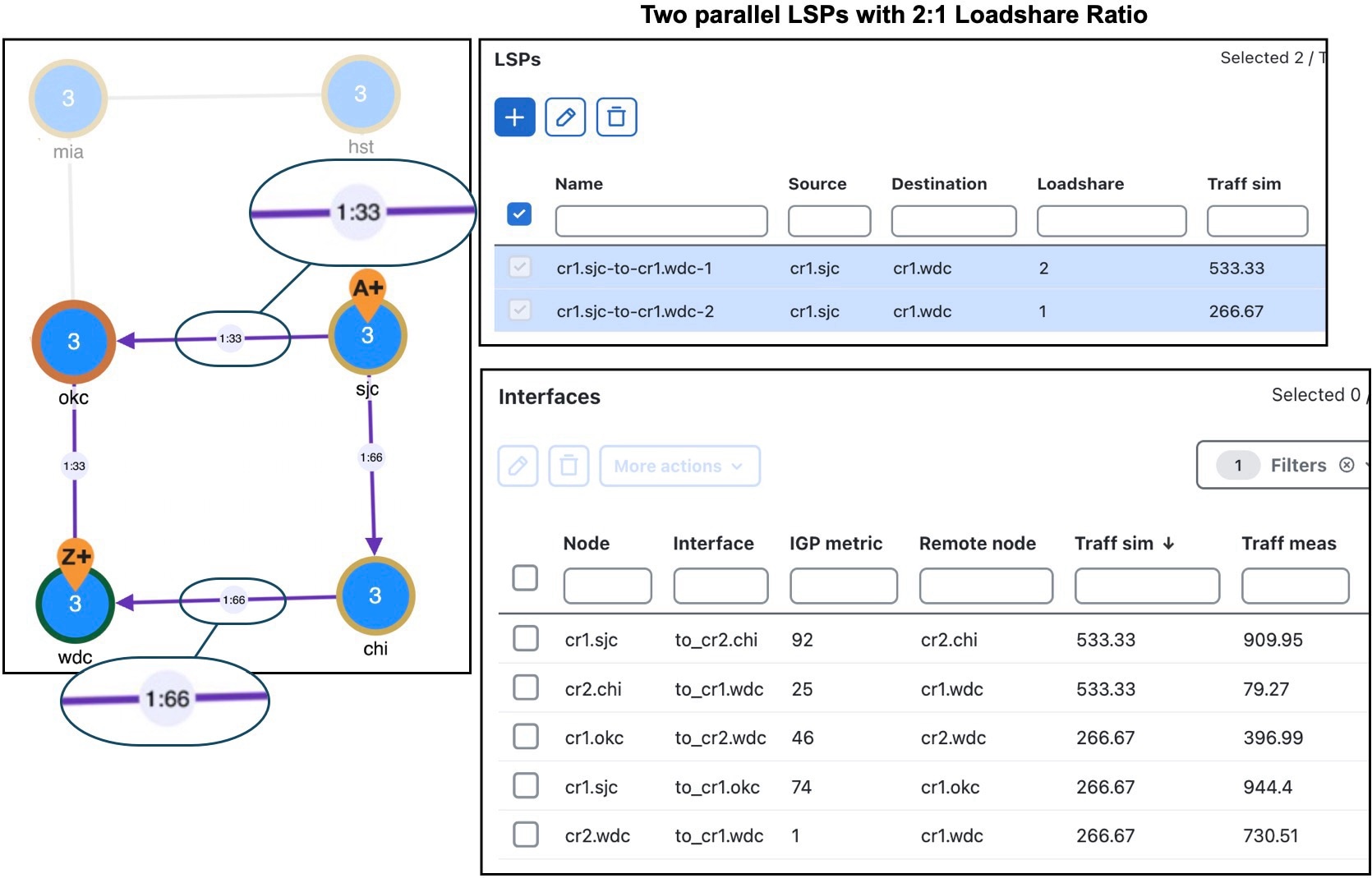
Each LSP has a path showing the percentage of traffic that crosses the LSP as a result of the Loadshare value for that LSP. The format is <path option>:<loadshare percentage>. Although loadshare applies only to path option 1, the LSP itself might be routed along a different path.
Note that this percentage may or may not be the same as the Loadshare value in the LSPs table. This is because the Loadshare value is relative to the other Loadshare values for parallel LSPs. For this reason, if manually editing the Loadshare property, we recommend that you consider the entire set of parallel LSPs. Note also that because an LSP can be in multiple sets of parallel LSPs, the percentage on its path can differ.
To optimize these Loadshare values, use the LSP Loadshare Optimization tool. For information, refer to LSP loadshare optimization.