Cisco Crosswork Planning Design 7.2.x User Guide

PDF

Cisco Crosswork Planning Design 7.2.x User Guide

Create external endpoints and add members

Want to summarize with AI?

Log in

Explains how to configure external endpoints and add their members within your network design plan.


Use this task to enable traffic routing and demand management by defining external endpoints and their members in a network design plan.

The recommended method of creating external endpoint members is to do so while creating the associated external endpoint.

Procedure

1.

Open the plan file (refer to Open plan files). It opens in the Network Design page.

2.

From the toolbar, choose Actions > Insert > Demands > External endpoints.

Alternatively, in the Network Summary panel, click Add icon in the External endpoints tab.

The External endpoints tab is available under the More tab. If it is not visible, then click the Show/hide tables icon () and check the External endpoints check box.

3.

In the Name field, enter a unique external endpoint name.

4.

To add a new member, click Add icon. To edit an existing member, select the member from the list and click Edit icon.

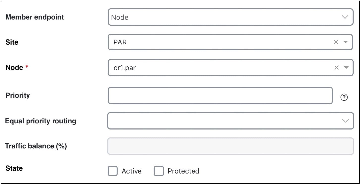
An External Endpoint Member page opens (refer to External endpoint member settings). Specify the parameters described in External endpoint member attributes and click Add.
5.

Click Add in the Add External Endpoint page.


External endpoint member attributes

Each member is assigned properties that prioritize traffic entering and exiting that member, in which order to fail over to another member, and how to distribute traffic for members of equal priority. These properties are set when you create the member. All members appear in the External endpoint members table.

Figure 1. External endpoint member settings
External endpoint members settings
  • Member endpoint: Defines whether the member is a node, AS, or external node through an AS.

    • For nodes, choose the site and node name.

    • For interfaces, choose the site, node, and interface. Using an interface lets you specify the exact interface on which the demand traffic is going into or out of a node.

    • For ASes, choose the AS name, and select either the “(None)” option or a node name within the AS. The “(None)” option routes traffic evenly across the entire AS.

  • Priority: The sequential order in which external endpoint members are used in simulations if failures occur.

  • Equal priority routing: If members have the same priority, this property identifies how the traffic is distributed. Select from these options:

    • Shortest Path: Use the member that results in the use of shortest path between source and destination.

      Note
      Members within an external endpoint that have the same priority must either all be Shortest Path or none of them be Shortest Path.

      If a member is using the shortest path, the Traffic balance (%) field is displayed as disabled.

    • Fix Traffic: Set the traffic across members of equal priority as defined in the Traffic balance (%) field.

    • Deduce Traffic: Behaves like Fix Traffic by setting traffic across members of equal priority as defined in the Traffic balance (%) field. However, upon running the Demand deduction tool, the Traffic balance (%) field is updated based on the measured traffic in the network. Note that Demand deduction only estimates the traffic balances for external endpoints with a priority that is in use in the current no-failure simulation. Therefore, Deduce Traffic is typically set to Priority 1.