Cisco Crosswork Planning Design 7.2.x User Guide

PDF

Cisco Crosswork Planning Design 7.2.x User Guide

SR-TE bandwidth optimizations

Want to summarize with AI?

Log in

Describes how SR-TE bandwidth optimization manages network congestion by rerouting demands and using efficient label-switched paths under defined constraints.


The goal when reducing traffic is to reroute as few demands as possible. This is achieved by creating private SR LSPs for demands. The SR-TE BW optimization tool also creates LSP paths and segment lists for these LSP paths with the fewest node or interface segment list hops possible, with a maximum of three hops. The final hop is either a node hop or interface whose remote node is the destination of the LSP.

The SR-TE BW optimization tool operates on a set of constraints that determine which paths are selected, whether demands and LSPs can be rerouted, and whether demand latency bounds can be surpassed. If the traffic cannot be reduced to below the threshold given these constraints, private SR LSPs are still created to route demands to reduce congestion as much as possible. If interface utilization surpasses the threshold prior to the optimization, it does not go higher. Utilization of non-congested interfaces might increase, though these will not surpass the threshold.

The tool reroutes existing SR LSPs only if they are private to a demand.

Note

The SR-TE BW optimization tool supports Inter-Area functionality.

Operating modes for SR-TE bandwidth optimization

The SR-TE BW optimization tool runs in two modes:

  • Analysis: The SR-TE BW optimization analysis tool performs multiple optimizations, one for each failure scenario within the specified failure set. The results of these optimizations are aggregated in a report. For more information on how to run this tool, refer to Analyze the congestion under different failure sets.

  • Operation: The SR-TE BW optimization operation tool performs an optimization using a specified set of constraints. For more information on how to run this tool, refer to Optimize SR-TE bandwidth.

An output plan file is generated with the optimization results. Only a single state of the network is considered. For example, if no objects are failed in the input plan file, the optimization is performed for normal operation. If a circuit is failed in the input plan file, the optimization is performed considering this particular failure scenario.


SR-TE bandwidth optimization input parameters

To perform the SR-TE bandwidth optimization, you must specify key input options that determine how traffic is managed, rerouted, and constrained within the network.

Interface utilization thresholds

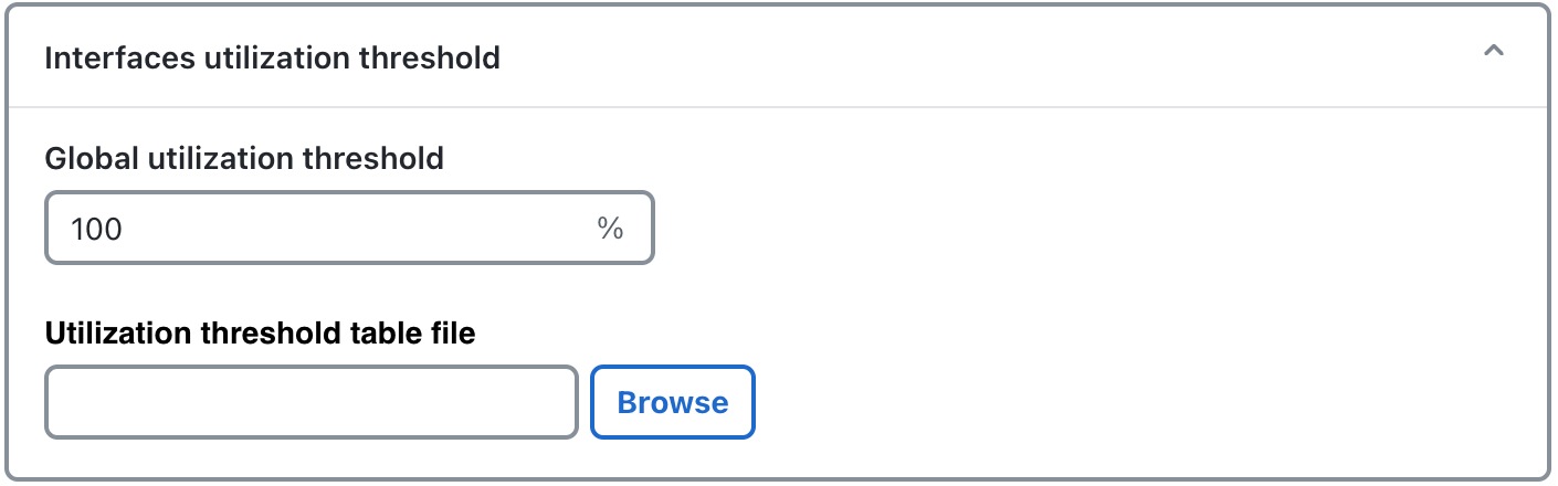
Interface utilization thresholds define the maximum allowed usage level for network interfaces. You can specify utilization threshold of an interface using the SR-TE BW optimization tool. If the utilization for an interface is larger than this threshold value, then that interface is considered to be congested, and the tool reduces traffic on the link.

Figure 1. Interface utilization threshold panel
Interface utilization threshold options
  • Global utilization threshold: Use this option to specify the global threshold value which applies to all interfaces on the network.

  • Utilization threshold tables file: Use this option to upload Utilization threshold tables file which is a .txt file. This file contains the threshold value for a specific interface.

    The file contains a table called <InterfaceThresholds> which has the threshold values defined and separated using tabs. The table has three columns: Node, Interface, and Threshold.

    Example: Refer to this sample table:

    <InterfaceThresholds>
    Node	Interface	Threshold
    cr1.nyc	to_cr2.wdc	70

    This table specifies that utilization on interface to_cr2.wdc from cr1.nyc must be less than 70 percent.

    Use the Browse button to upload the Utilization Threshold Tables file. Uploading this file is optional, but when the interface threshold is specified using this file, the tool aims to reduce the utilization on this link to the specified threshold.


Rerouting demands

The analysis and operation modes provide several configurable options for rerouting demands within the network. You can use these options determine how demands are selected, routed, and whether specific constraints such as latency or previously optimized paths are enforced.
Figure 2. Rerouting demands section
Rerouting demands options
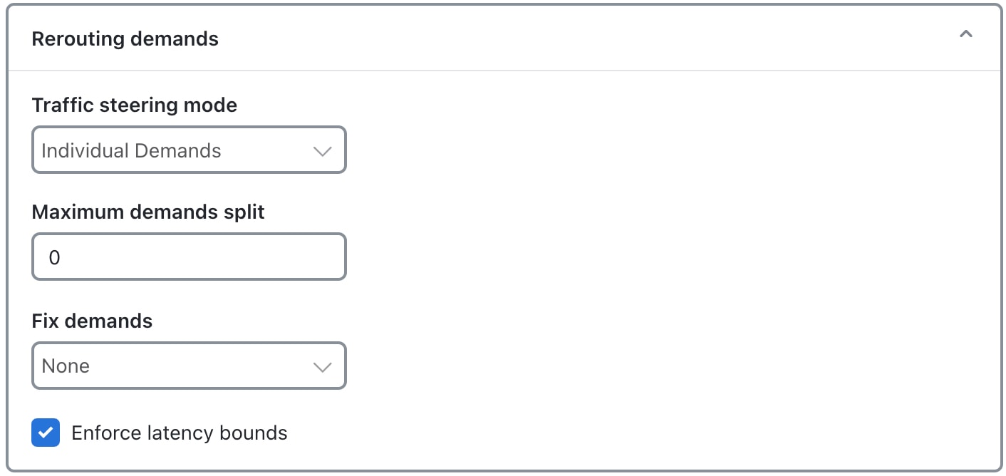
  • Traffic steering mode: If you choose Individual Demands, each demand is individually carried by a private LSP. If you choose Autoroute, multiple demands can be carried by a non-private Autoroute LSP.

  • Maximum demands split: Use this option to split demands into smaller demands. If n is the value entered, the demands are split into 'n+1' smaller demands. The default value is 0.

  • Fix demands: Selected or tagged demands are not rerouted. This constraint is useful, for example, when you have previously optimized specific LSPs within the network and want to maintain the route of one or more existing demands.

  • Enforce latency bounds: If checked, demands cannot surpass their configured latency bound. This property is set in the Edit Demand window. If the latency of rerouted demands exceeds the configured bound, the tool does not reroute demands on congested interfaces.


Bandwidth constraint options

Both analysis and operation modes use these options for specifying bandwidth constraints.

Figure 3. Constraints section
Constraints
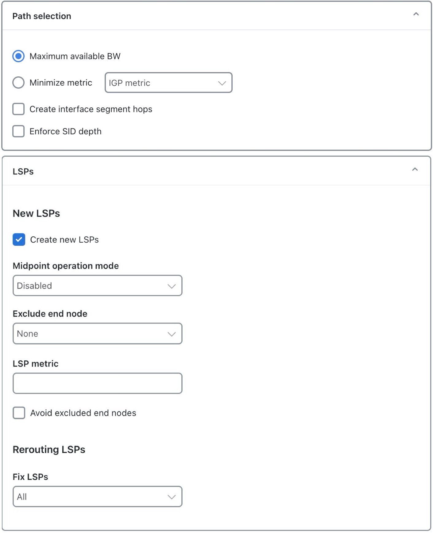
  • Path Selection: When choosing demand routes, the SR-TE BW Optimization tool uses one of these criteria:

    • Maximize available BW: Paths are optimized to achieve the highest available bandwidth on interfaces (Capacity Sim - Traff Sim).

    • Minimize metric: Paths are optimized to minimize the sum of the metrics along the path with respect to Delay, TE Metric, or IGP Metric. These properties are configurable from an interface Properties window, and delays can also be set in a circuit Properties window.

    • Create interface segment hops: If checked, the tool considers interface hops when trying to drive down utilization.

    • Enforce SID depth: If checked, the number of hops in the optimized segment lists are bound by the Max SID Depth defined at the source of the lists.

  • LSPs:

    • Create new LSPs: If checked, new private SR LSPs with optimized routing can be created. If unchecked, new LSPs are not created.

      • Midpoint operation mode

        • Disabled: Default mode indicating that the new SR LSP source/destination nodes must match demand source/destination nodes.

        • Demand endpoint proximity: Specifies that the new SR LSP source/destination nodes may differ from the demand source/destination nodes. Source/Destination nodes closer to demand endpoints are selected.

        • Congestion proximity: Specifies that the new SR LSP source/destination nodes may differ from the demand source/destination nodes. Source/Destination nodes closer to congestion points are selected.

      • Exclude end node: Nodes selected are not considered as source/destinations nodes for SR LSPs. Default value is None. The nodes selected here are ignored if Midpoint operation mode is set to Disabled.

      • LSP metric: When specified, LSPs created by the tool will have their Metric Value set to the specified value.

      • Avoid excluded end nodes: If the option is selected, the specified nodes will not be included in the newly created LSPs.

    • Rerouting LSPs

      • Fix LSPs: Controls whether or not LSP routes can be modified. This constraint is useful if you want to reroute existing LSPs to mitigate congestion.


Optimize SR-TE bandwidth

Bandwidth optimization helps ensure efficient use of available network resources. Complete these steps to configure the optimization process, specify the thresholds, constraints, and segment hop requirements.

Procedure

1.

Open the plan file (refer to Open plan files). It opens in the Network Design page.

From the toolbar, choose Actions > Tools > SR LSP optimization > SR-TE BW optimization operation.

Alternatively, choose Preset workflows > Perform optimization, select SR LSP Optimization as the optimization type, select SR-TE BW optimization operation from the drop-down list, and click Launch.

2.

Select whether to optimize bandwidth for all interfaces or selected interfaces.

3.

Specify the utilization threshold of an interface and the routing demand options. For more information, refer to Interface utilization thresholds and Rerouting demands.

4.

(Optional) In the Tag updated LSPs with field, override the defaults for how LSPs are tagged (SRBWOpt).

5.

Specify constraints. For more information, refer to Bandwidth constraint options.

6.

Select the required segment hop constraints from the Node segment hop and Interface segment hop drop-down lists, and click Next.

7.

On the Run Settings page, choose whether to execute the task now or schedule it for a later time. Choose one of these Execute options:

  • Now: Choose this option to execute the job immediately. The tool runs and changes are applied to the network model immediately. A summary report appears. You can access the report any time later using Actions > Reports > Generated reports option.

  • As a scheduled job: Choose this option to execute the task as an asynchronous job. Set these options:

    • Priority: Select the priority of the task.

    • Engine profiles: Select the engine profile as needed. This section lists all the available asynchronous engine profiles.

    • Schedule: Set the time at which you want to run the tool.

    The tool runs at the scheduled time using the selected engine profile. You can track the status of the job at any time using the Job Manager page (from the main menu, choose Job Manager). Once the job completes, import the output plan file into user space to visualize it. For more information, refer to Access output plan files from job manager.

    Note
    Ensure that you save the plan file before you schedule the job. Any unsaved changes in the plan file are not considered when you run the tool as a scheduled job.
8.

(Optional) If you want to display the result in a new plan file, specify a name for the new plan file in the Display results section.

In the previous step:
  • If you have selected to run the task immediately, by default, the changes are applied on the current plan file. If you want to display the results in a new file, select the Display results in a new plan file check box and enter the name of the new plan file.

  • If you have scheduled the task to run at a later time, by default, the results are displayed in the Plan-file-1. Update the name, if required.

9.

Submit your changes.


Analyze the congestion under different failure sets

Use this task to perform multiple optimizations, one for each failure scenario within a specified failure set. The analysis aggregates results, helping you identify configurations that minimize congestion under different failure scenarios.

Procedure

1.

Open the plan file (refer to Open plan files). It opens in the Network Design page.

2.

From the toolbar, choose any of these these options:

From the toolbar, choose Actions > Tools > SR LSP optimization > SR-TE BW optimization analysis.

Alternatively, choose Preset workflows > Perform optimization, select SR LSP Optimization as the optimization type, select SR-TE BW optimization analysis from the drop-down list, and click Launch.

3.

By default, the analysis tool presents you with the bandwidth optimization options. Configure these options, as required. For more information, refer to Optimize SR-TE bandwidth.

4.

Click Next to go to the Advanced Setting page. Click the Failure set section.

5.

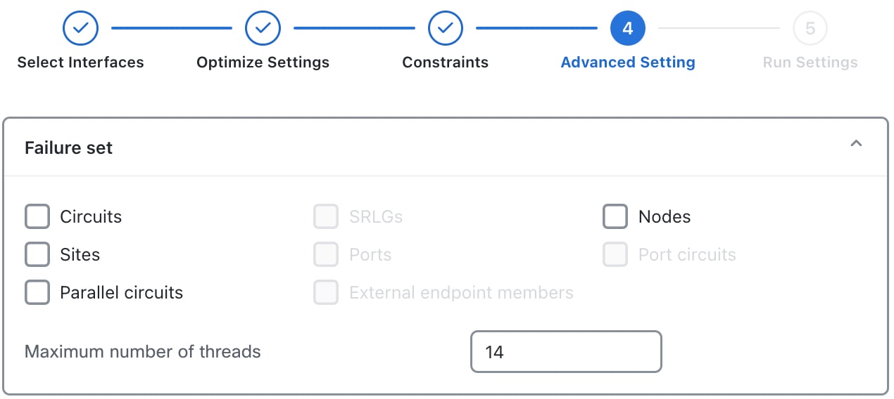
Select the failure sets that you want the optimizer to consider (circuits, nodes, sites, and so on).

Entries appear dimmed if they are not available in your design plan.

Figure 4. Failure sets panel
Failure sets options
6.

(Optional) Specify the maximum number of threads.

By default, the optimizer tries to set this value to the optimal number of threads based on the available cores.

7.

Select the required segment hop constraints from the Node segment hop and Interface segment hop drop-down lists, and click Next.

8.

On the Run Settings page, choose whether to execute the task now or schedule it for a later time. Choose one of these Execute options:

  • Now: Choose this option to execute the job immediately. The tool runs and changes are applied to the network model immediately. A summary report appears. You can access the report any time later using Actions > Reports > Generated reports option.

  • As a scheduled job: Choose this option to execute the task as an asynchronous job. Set these options:

    • Priority: Select the priority of the task.

    • Engine profiles: Select the engine profile as needed. This section lists all the available asynchronous engine profiles.

    • Schedule: Set the time at which you want to run the tool.

    The tool runs at the scheduled time using the selected engine profile. You can track the status of the job at any time using the Job Manager page (from the main menu, choose Job Manager). Once the job completes, import the output plan file into user space to visualize it. For more information, refer to Access output plan files from job manager.

    Note
    Ensure that you save the plan file before you schedule the job. Any unsaved changes in the plan file are not considered when you run the tool as a scheduled job.
9.

Submit your changes.


Bandwidth optimization report

After completion of a basic optimization, the SR-TE BW optimization tool generates a summary report to identify key changes due to the optimization.

The tool tags the LSPs with SRBWopt and generates a new plan file with an -SRBWopt suffix. This plan file opens, showing the LSPs table that is filtered to these rerouted (and newly tagged) LSPs. Saving this plan file then simplifies the process of identifying which LSPs to reconfigure in the network. Both the tags and the new plan file names are editable.

After running the bandwidth optimization, the optimizer creates a summary report that includes:

  • Number of interfaces that exceeded the utilization both before and after the optimization

  • Maximum utilization both before and after the optimization

  • Number of demands that were rerouted

  • Number of LSPs that were created and rerouted

  • Average segment list length

  • Number of latency bound violations both before and after the optimization