Cisco Crosswork Planning Design 7.2.x User Guide

PDF

Cisco Crosswork Planning Design 7.2.x User Guide

Circuit Style RSVP LSPs

Want to summarize with AI?

Log in

Introduces CS-RSVP LSP simulations and outlines paths, restore calculation, biased routing, creation, optimization, diagnostics, reporting, examples, and visualization workflows for planning.


Circuit Style RSVP (CS-RSVP) LSPs are logical entities that bundle two uni-directional RSVP LSPs with the same endpoints to form bi-directional RSVP LSPs. This allows traffic to consistently travel in both directions between the endpoints. Cisco Crosswork Planning supports creating and visualizing CS-RSVP LSPs.

CS-RSVP LSP key features

These are the key features of CS-RSVP LSPs:

  • Persistent end-to-end traffic engineered paths: provides predictable and identical latency in both directions.

  • Strict bandwidth commitment: ensures no impact on the SLA due to changing network load from other services.

  • End-to-end protection and restoration mechanism: implements robust protection and restoration mechanisms.

  • Monitoring and maintenance of path integrity: continuously monitors and maintains the integrity of the paths.

  • Data plane resilience: ensures the data plane remains operational even if the control plane is down.


CS-RSVP LSP paths

To improve redundancy, a CS-RSVP LSP has four paths: Working (W), Protect (P), and the corresponding restore paths, named WR and PR respectively.

The paths are categorized as W, P, and restore paths according to the "Path option" field in the LSP paths table. From the lowest to the highest path option, they are classified as W, P, WR, and PR, respectively.
  • Working path (W): This is the path with the lowest path option value.

  • Protect path (P): This is the path with the second lowest path option value.

  • Restore paths (WR and PR): These paths are calculated dynamically when the corresponding W or P is down, considering disjointness constraints. By default, node-disjoint is considered. If node-disjointness is not possible, it automatically falls back to link-disjointness. If an SRLG-disjoint is specified, it takes precedence over node and link disjointness. If the system cannot find a disjointed restore path, it keeps the corresponding CS-RSVP LSP operational without backup path protection.

    Restore paths are calculated based on the "Protected by" field of the LSP Path. For more information, refer to Restore path calculation.

Cisco Crosswork Planning ensures that both W and P paths have a fully explicit path defined in the named path.


Restore path calculation

A restore path calculation is a method in CS-RSVP LSP configuration that

  • determines how traffic is rerouted when a primary LSP path fails

  • identifies which LSPs serve as working, protect, and restore paths under different failure scenarios, and

  • uses attributes like Protected by and Routed to control path behavior.

The idea of a restore path is to protect the path that carries traffic. This is defined in the Protected by field of the LSP path. This field specifies which alternative LSPs can take over if the primary (working) path fails. The "Routed" field shows whether a specific LSP is actively routing traffic.

Example

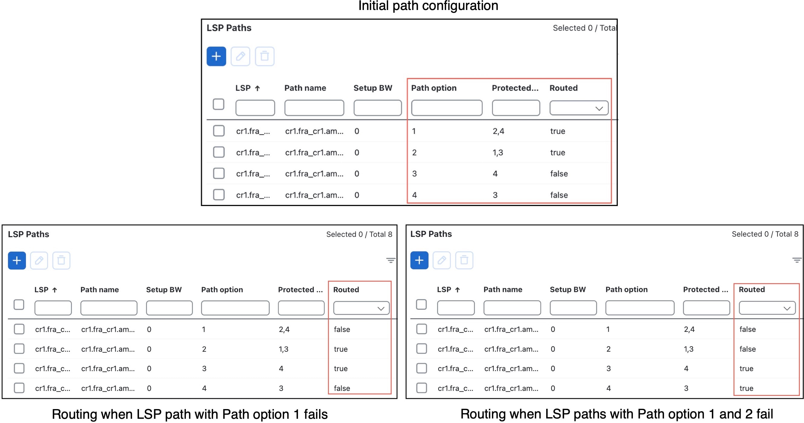
Restore path calculation example shows the path configuration of the four LSP paths associated with a CS-RSVP LSP. Consider LSP path with path option 1 as LSP-1, Path option 2 as LSP-2, Path option 3 as LSP-3, and Path option 4 as LSP-4. Observe that LSP-1 and LSP-2 have the Routed option as "true", and LSP-3 and LSP-4 have this option as "false".

These steps describe how the restore path is calculated:

  1. If LSP-1 fails, the traffic shifts to LSP-2 and LSP-3 becomes the Protect path. This happens because the Protected by field for LSP-1 is set to 2, 4, indicating that when LSP-1 goes down, LSP-2 becomes the Working path and LSP-4 becomes the restore path. Since LSP-2 has the Protected by field as 1, 3 and since LSP-1 is already down, the LSP-3 becomes the Protect path.

    Notice that the Routed column value for LSP-1 changes to "false", and LSP-2 and LSP-3 have this value as "true".

  2. Now, if LSP-2 goes down, traffic shifts to LSP-3 and LSP-4 becomes the Protect path. This happens because the LSP-2 has 1, 3 as the Protected by option. Since LSP-1 is down as indicated in Step 1, LSP-3 becomes the Working path. LSP-4 becomes the Protect path because LSP-3 has the Protected by field as 4.

    Observe that the Routed column value for LSP-2 changes to "false", and LSP-3 and LSP-4 have this value as "true".

Figure 1. Restore path calculation example
Restore path calculation example

How CS-RSVP LSP path simulation works

Summary

Cisco Crosswork Planning performs these checks to determine if the path is routable:

Workflow

  1. The explicit paths go through the same hops in both directions. This check applies only to restore paths routed dynamically.
  2. The explicit path can reach the endpoints in both directions. Note that the configuration check is not performed.
  3. The path has enough bandwidth to satisfy the setup bandwidth requirement. Note that asymmetric configuration is not checked.
  4. If W or P is down, Cisco Crosswork Planning calculates the corresponding restore path. If the Biased routing option in the Network Options page is enabled, the restore path is calculated by reusing the existing reserved resources. If Biased routing is disabled, the restore paths are calculated regularly. For more information, refer to Configure biased routing.
  5. When routing an LSP path, the route follows the hops defined in the named path. W and P have fully explicit path listed in the named path. If the named path is not explicit or unroutable, the LSP path becomes unrouted. Paths are found dynamically only for restore paths.
  6. When routing the restore path, node disjointness and link disjointness from the existing path carrying traffic are considered by default. If node disjointness is not possible, then link disjointness is considered. SRLG disjointness is considered if SRLG disjointness is configured at the LSP level.

Configure biased routing

Use this task to set biased routing options that influence CS-RSVP LSP restore path calculation during simulations.

In normal routing, restore path is not required to follow the corresponding W or P path as much as possible. The restore path is routed regularly with the constraint of disjointness.

In Biased Routing, the restore paths (WR and PR) reuse the corresponding W and P paths as much as possible, while ensuring that the total metric of the restore path does not exceed the maximum metric constraint. If biased routing is disabled, the restore paths are calculated regularly.

Procedure

1.

Open the plan file (refer to Open plan files). It opens in the Network Design page.

2.

In the toolbar, click or choose Actions > Edit > Network options.

The Network options page opens.

3.

Under the Simulation tab, in the Metric constraint section, enable biased routing.

  1. Check the Biased routing check box.

  2. In the Maximum metric constraint field, enter the maximum allowable metric for the restore path. It can be set to an extremely large value if this constraint is not required.

4.

Save your changes.


Create CS-RSVP LSPs

Use this task to create CS-RSVP LSPs by configuring participating RSVP LSPs, co-routing settings, association IDs, and path roles.

You can create CS-RSVP LSPs in the Cisco Crosswork Planning Design application either manually or with the CS-RSVP LSP optimizer tool.

This task describes the manual method. For the optimizer method, refer to Create CS-RSVP LSPs using the optimizer tool.

Before you begin

In the Add/Edit LSP page of the two RSVP LSPs participating in the CS-RSVP LSP, ensure that:

  • The Co-routed option is enabled. This option is available in the CSPF section of the Add/Edit LSP page.

  • They have the same Association ID.

Procedure

1.

Open the plan file (refer to Open plan files). It opens in the Network Design page.

2.

From the toolbar, choose Actions > Insert > LSPs > CS-RSVP LSP.

Alternatively, in the Network Summary panel on the right side, click Add icon in the CS-RSVP LSPs tab.

The CS-RSVP LSPs tab is available under the More tab. If it is not visible, then click the Show/hide tables icon () and check the CS-RSVP LSPs check box.

3.

In the Node A and Node B sections, choose the endpoints of the CS-RSVP LSP.

4.

Enter the details in these fields.

  • Association ID: This field is used to associate two RSVP LSPs. This is a required field.

  • Source address: This field represents the source address for the bidirectional association. This is an optional field. If you do not enter a value, it defaults to an empty value.

  • Global ID: This field specifies the global ID for the association's global source. This is an optional field. If you do not enter a value, it defaults to an empty value.

  • Routed: This field indicates whether the CS-RSVP LSP is routable. It derives its value based on specific criteria and cannot be manually set.

5.

Click Add.


CS-RSVP LSP optimizer

CS-RSVP LSP optimizer is a Cisco Crosswork Planning tool that

  • helps to create, find, and optimize CS-RSVP LSPs based on specified endpoint pairs, association ID, source address, and global ID

  • optimizes both existing and newly created CS-RSVP LSPs together, and

  • allows you to choose to optimize only the existing LSPs or only the newly created ones


Create CS-RSVP LSPs using the optimizer tool

If CS-RSVP LSPs do not exist, the optimizer creates the corresponding LSPs based on the given configurations. The configuration process involves specifying several key parameters as described in this procedure.

The tool creates two LSP paths as W and P for each LSP. It creates the hops of each path as the named path of the corresponding LSP path. In addition to W and P paths, it also creates two additional paths, WR and PR. These additional paths do not have named paths and are associated with their respective W and P paths.

Procedure

1.

Open the plan file (refer to Open plan files). It opens in the Network Design page.

2.

From the toolbar, choose Actions > Tools > CS-RSVP LSP optimizer.

3.

(Optional) If you want to optimize the existing CS-RSVP LSPs, select them and click Next.

4.

Click Create in the Create new CS-RSVP LSPs page.

5.

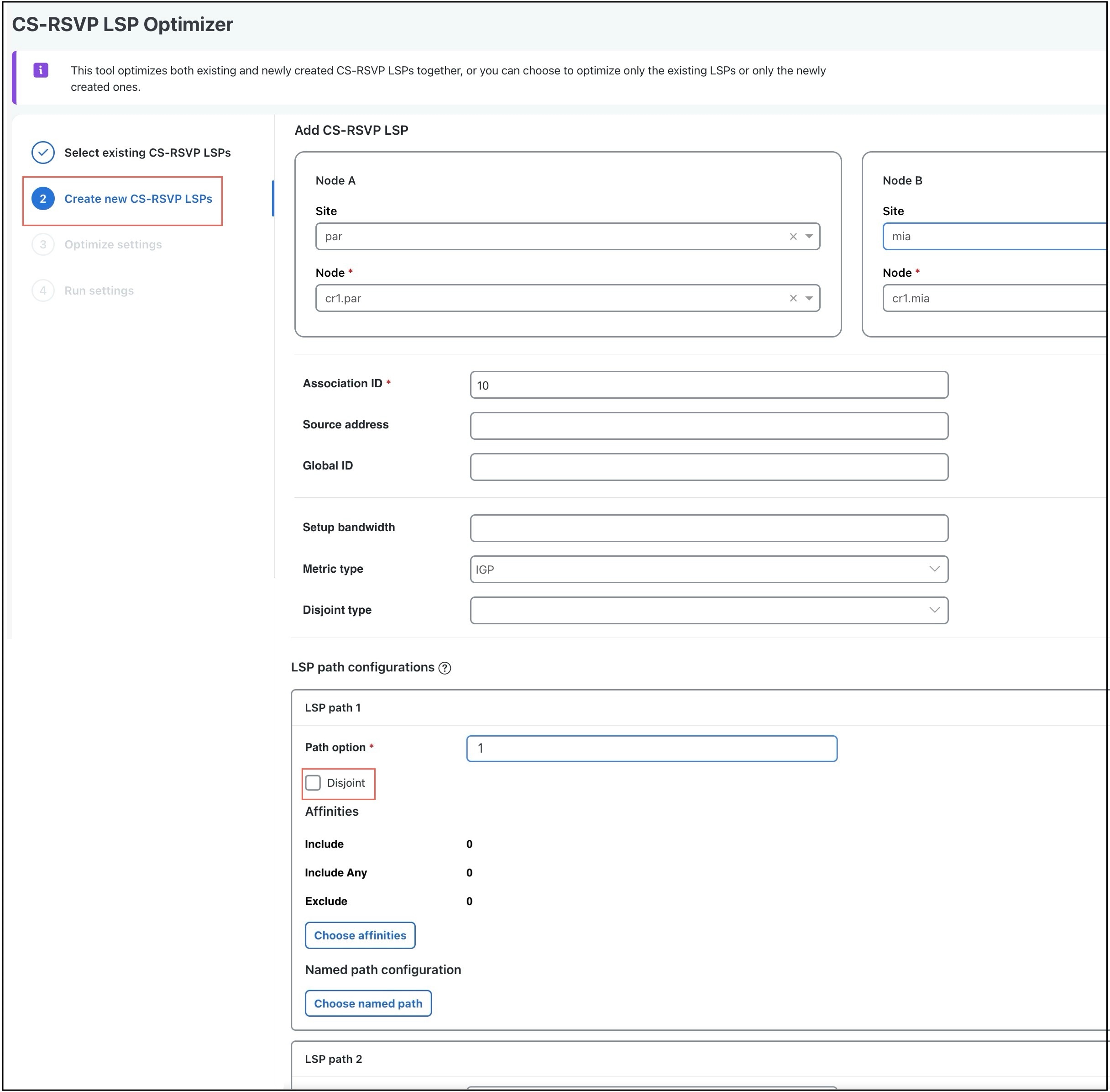
Enter the details in the required fields. In the LSP path configurations section, define the configurations for the four LSP paths: W, P, WR, and PR. For field descriptions, refer to Table 1.

Figure 2. Create new CS-RSVP LSPs page
Create new CS-RSVP LSPs page
6.

Click Save. Then, select the newly created CS-RSVP LSP and click Next.

To create additional CS-RSVP LSPs, click Add icon.

7.

Select the interfaces you want to exclude from the route calculation of CS-RSVP LSPs.

8.

On the Run Settings page, choose whether to execute the task now or schedule it for a later time. Choose one of these Execute options:

  • Now: Choose this option to execute the job immediately. The tool runs and changes are applied to the network model immediately. A summary report appears. You can access the report any time later using Actions > Reports > Generated reports option.

  • As a scheduled job: Choose this option to execute the task as an asynchronous job. Set these options:

    • Priority: Select the priority of the task.

    • Engine profiles: Select the engine profile as needed. This section lists all the available asynchronous engine profiles.

    • Schedule: Set the time at which you want to run the tool.

    The tool runs at the scheduled time using the selected engine profile. You can track the status of the job at any time using the Job Manager page (from the main menu, choose Job Manager). Once the job completes, import the output plan file into user space to visualize it. For more information, refer to Access output plan files from job manager.

    Note
    Ensure that you save the plan file before you schedule the job. Any unsaved changes in the plan file are not considered when you run the tool as a scheduled job.
9.

(Optional) If you want to display the result in a new plan file, specify a name for the new plan file in the Display results section.

In the previous step:
  • If you have selected to run the task immediately, by default, the changes are applied on the current plan file. If you want to display the results in a new file, select the Display results in a new plan file check box and enter the name of the new plan file.

  • If you have scheduled the task to run at a later time, by default, the results are displayed in the Plan-file-1. Update the name, if required.

Observe these changes:

  • The newly created CS-RSVP LSPs are available on the CS-RSVP LSPs table with NewCSRSVPLSPs as tags.

  • The corresponding LSPs are available on the LSPs table.

  • The corresponding LSP paths are available on the LSP paths table. Note that the LSP paths are created based on the Path option values you entered and the Protected by field is automatically calculated.


Optimize existing CS-RSVP LSPs with the optimizer tool

If CS-RSVP LSPs already exist, the optimizer can optimize them based on the current configurations and requirements. Use this task to optimize the existing CS-RSVP LSPs using the CS-RSVP LSP optimizer tool.

Procedure

1.

Open the plan file (refer to Open plan files) with CS-RSVP LSPs. It opens in the Network Design page.

2.

From the toolbar, choose Actions > Tools > CS-RSVP LSP optimizer.

3.

Select the existing CS-RSVP LSPs you want to optimize and click Next.

4.

(Optional) If you want to create new CS-RSVP LSPs, click Create and configure the required parameters. For more information, refer to Create CS-RSVP LSPs using the optimizer tool.

5.

Select the interfaces you want to exclude from the route calculation of CS-RSVP LSPs.

6.

Click Next.

7.

On the Run Settings page, choose whether to execute the task now or schedule it for a later time. Choose one of these Execute options:

  • Now: Choose this option to execute the job immediately. The tool runs and changes are applied to the network model immediately. A summary report appears. You can access the report any time later using Actions > Reports > Generated reports option.

  • As a scheduled job: Choose this option to execute the task as an asynchronous job. Set these options:

    • Priority: Select the priority of the task.

    • Engine profiles: Select the engine profile as needed. This section lists all the available asynchronous engine profiles.

    • Schedule: Set the time at which you want to run the tool.

    The tool runs at the scheduled time using the selected engine profile. You can track the status of the job at any time using the Job Manager page (from the main menu, choose Job Manager). Once the job completes, import the output plan file into user space to visualize it. For more information, refer to Access output plan files from job manager.

    Note
    Ensure that you save the plan file before you schedule the job. Any unsaved changes in the plan file are not considered when you run the tool as a scheduled job.
8.

(Optional) If you want to display the result in a new plan file, specify a name for the new plan file in the Display results section.

In the previous step:
  • If you have selected to run the task immediately, by default, the changes are applied on the current plan file. If you want to display the results in a new file, select the Display results in a new plan file check box and enter the name of the new plan file.

  • If you have scheduled the task to run at a later time, by default, the results are displayed in the Plan-file-1. Update the name, if required.

Observe that the selected CS-RSVP LSPs are updated and have the tagsUpdatedCSRSVPLSPs.


CS-RSVP LSP configuration parameters

This table lists the parameters to configure when creating CS-RSVP LSPs using the optimizer tool.

Table 1. CS-RSVP LSP configuration parameters

Field

Description

Node A and Node B

These fields indicate the endpoints of the LSPs corresponding to the CS-RSVP LSP.

Association ID

This field is used to associate two RSVP LSPs. This is a required field.

Source address

This field represents the source address for the bidirectional association. This is an optional field. If you do not enter a value, it defaults to an empty value.

Global ID

This field specifies the global ID for the association's global source. This is an optional field. If you do not enter a value, it defaults to an empty value.

Setup bandwidth

This field indicates the amount of traffic the source nodes requests for this CS-RSVP LSP in Mbps. This is an optional field.

Metric type

This field indicates the metric type for route calculation. Choose either IGP or TE as per your requirement.

Disjoint type

This field indicates the disjoint type to consider. Choose SRLGs to enable SRLG disjointness in addition to the default node and link disjointness.

LSP path configurations

Path option

This field specifies the path option of the LSP paths corresponding to the CS-RSVP LSP. The path with the lowest Path option value is assigned as the W path, the next lowest as P, the third lowest as WR, and the fourth lowest as the PR. Ensure that each LSP path has a unique Path option value.

For example, if the path options are 1, 2, 3, and 4, then the LSP path with Path option 1 is designated as W, path option 2 as P, path option 3 as WR, and path option 4 as PR.

Disjoint

This check box indicates whether to consider this LSP path for disjointness with any other LSP path that has this check box enabled. Ensure that exactly two LSP paths are configured as disjoint.

Affinities

This is an optional field. Click Choose affinities to assign affinities to the LSP paths.

Named path configuration

This is an optional field. Click Choose named path to assign named path configurations to the LSP paths.


CS-RSVP LSP simulation diagnostics

The CS-RSVP LSP simulation diagnostics tool in Cisco Crosswork Planning performs configuration and disjointness checks on the CS-RSVP LSPs.

Configuration check

The configuration check ensures that these properties of a given CS-RSVP LSP are identical on the associated RSVP LSPs:

  • Association ID, Source address, and Global ID

  • Setup bandwidth

  • LSP type and LSP path count

  • Protected by and Dynamic field configurations

  • Hold priority and setup priority

  • Named path, ensuring that Working and Protect paths have named paths

  • Source and Destination

  • Path options on LSP paths

The disjointness check ensures that all CS-RSVP LSPs in the network model are disjoint, meaning they do not share certain resources. This helps to maintain redundancy and avoid single points of failure.

The tool summarizes these violations:

  • SRLG disjointness violation (only for CS-RSVP LSP with SRLG disjointness configuration)

  • Node disjointness violation

  • Link disjointness violation

  • Node to link disjointness fallback


Run the CS-RSVP LSP simulation diagnostics tool

Use this task to run the CS-RSVP LSP simulation diagnostics tool and identify configuration, association, and path issues.

Procedure

1.

Open the plan file (refer to Open plan files) with CS-RSVP LSPs. It opens in the Network Design page.

2.

From the toolbar, choose Actions > Tools > Diagnostics > CS-RSVP LSP simulation.

3.

Click Proceed in the information dialog box.

A report is generated indicating the details of the failures.


CS-RSVP LSP simulation diagnostics report

Each time the CS-RSVP LSP simulation diagnostics tool is run, a report is automatically generated. You can access this information at any time by choosing Actions > Reports > Generated reports and then clicking the CS-RSVP LSP Simulation link in the right panel. Note that new reports replace the previous ones.

The Summary tab provides information on the number of failed CS-RSVP LSPs.

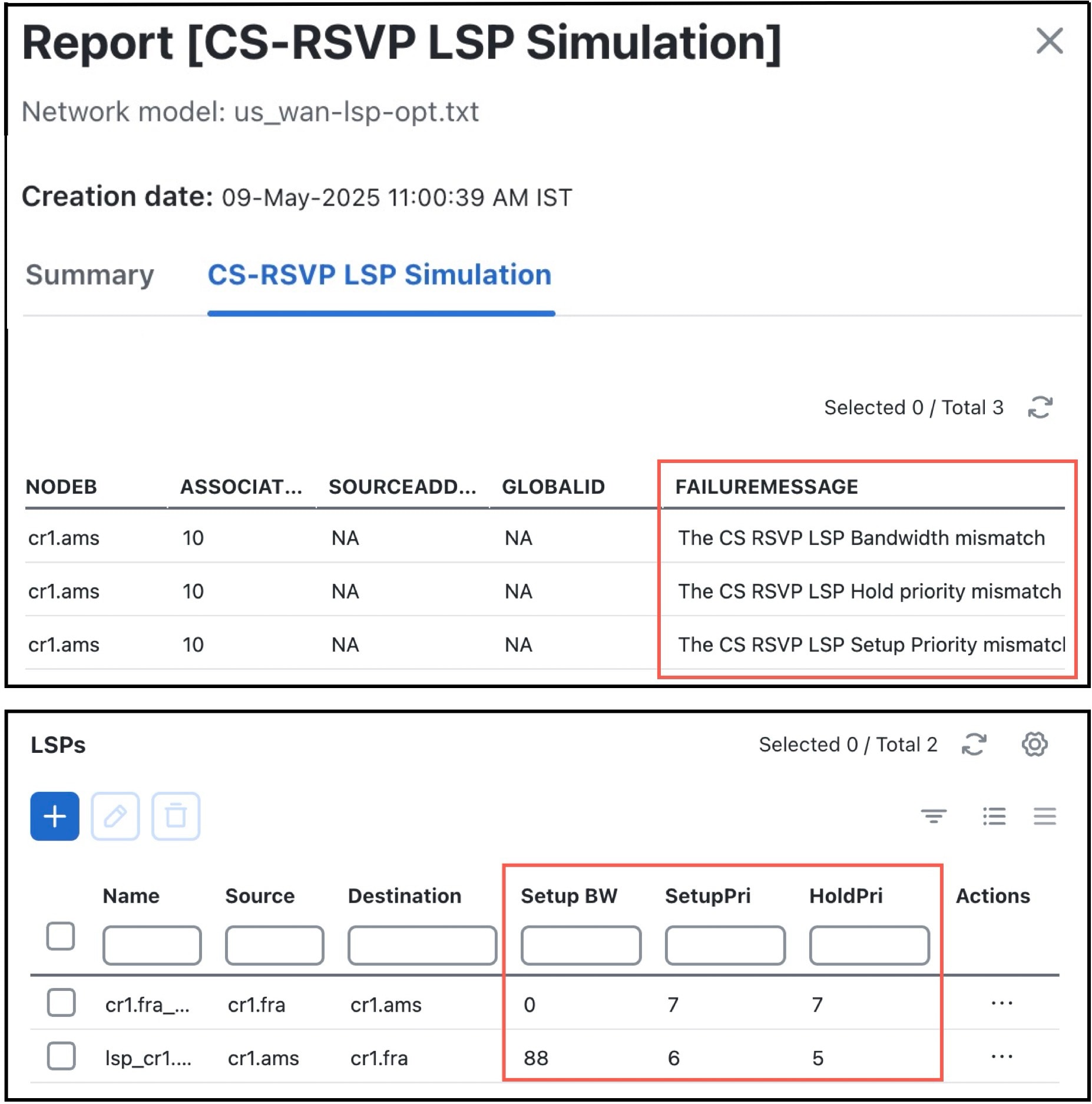
The CS-RSVL LSP simulation tab provides failure details. Expand the FAILUREMESSAGE column to view the failure messages.


CS-RSVP LSP simulation diagnostics example

The plan file has a CS-RSVP LSP with configuration issues, such as associated LSPs having different Setup priority, Hold priority, and Setup bandwidth. After running the CS-RSVP LSP simulation diagnostics tool, the generated report shows this information in the FAILUREMESSAGE column.

By filtering from the CS-RSVP LSPs table to the LSPs table, you can refer to that the values for these fields do not match.

Figure 3. CS-RSVP LSP simulation diagnostics report and mismatching LSPs

CS-RSVP LSP visualization

CS-RSVP LSPs are associated with LSPs and LSP paths. This section describes how to visualize:

  • CS-RSVP LSPs

  • LSPs associated with CS-RSVP LSPs

  • LSP paths associated with CS-RSVP LSPs


Visualize CS-RSVP LSPs

Use this task to visualize selected CS-RSVP LSPs in the network plot.

Procedure

1.

Open the plan file (refer to Open plan files) with CS-RSVP LSPs. It opens in the Network Design page.

2.

In the Network Summary panel on the right side, navigate to the CS-RSVP LSPs tab.

The CS-RSVP LSPs tab is available under the More tab. If it is not visible, then click the Show/hide tables icon () and check the CS-RSVP LSPs check box.

Note

You can select only one CS-RSVP LSP at a time to view on the network plot.

3.

Select the required CS-RSVP LSP from the list.

4.

Observe these in the network plot on the left side:

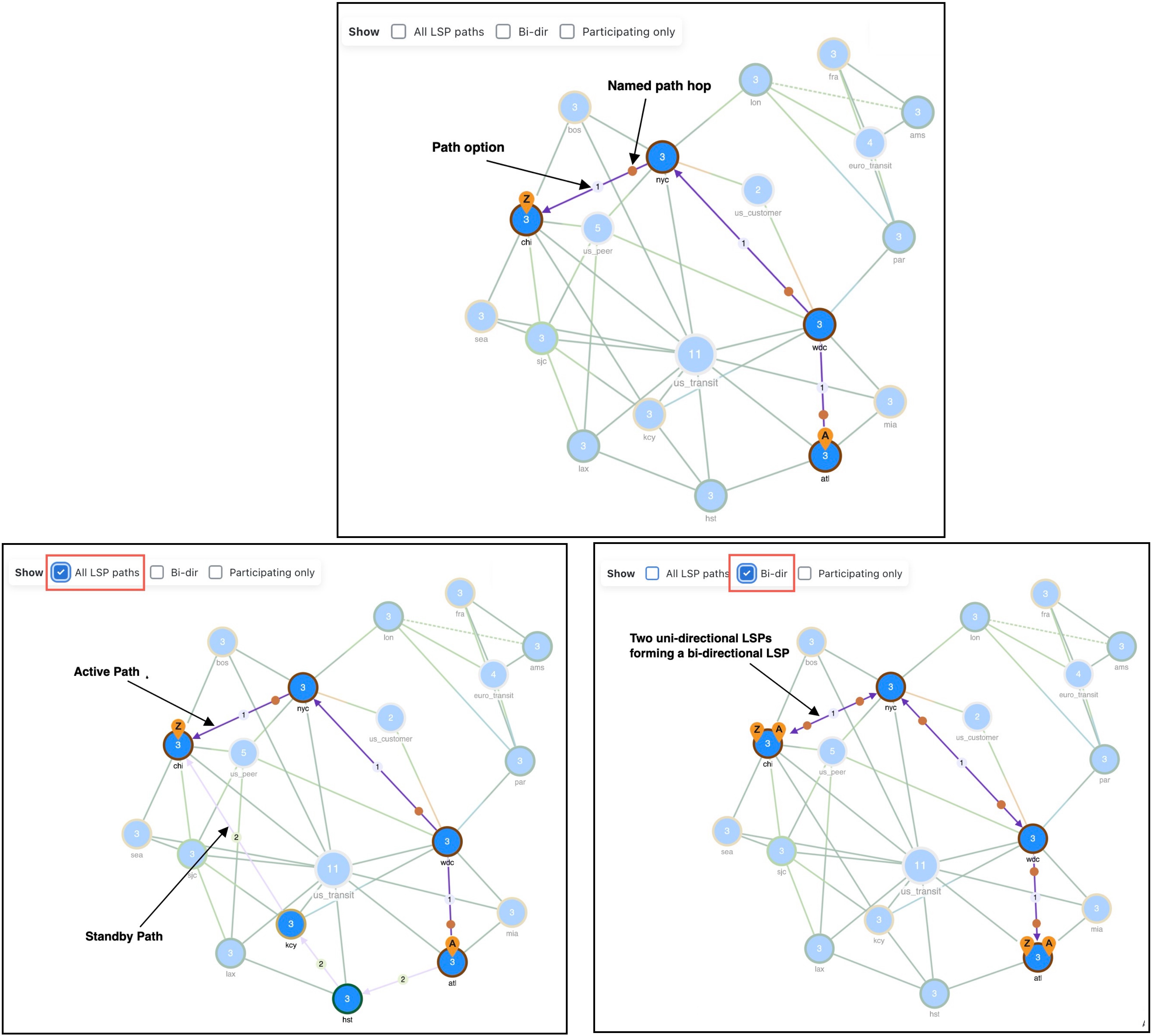
  • Both LSPs associated with the CS-RSVP LSP are plotted. The purple arrow indicates the LSP path is active (carrying traffic). The number on the path (here 1) is the path option. For example, refer to the first image in CS-RSVP LSP path visualization.

    A dim purple arrow indicates the standby path, which is an LSP path that is not a primary path and is set as a Standby path. To view the standby paths, check the All LSP paths check box in the network plot. For example, refer to the second image in CS-RSVP LSP path visualization.

  • The bi-directional LSPs are plotted when you check the Bi-dir check box in the network plot. For example, refer to the third image in CS-RSVP LSP path visualization.

Figure 4. CS-RSVP LSP path visualization
CS-RSVP LSP path visualization

Visualize LSPs associated with CS-RSVP LSPs

Use this task to visualize RSVP LSPs associated with selected CS-RSVP LSPs.

Procedure

1.

Open the plan file (refer to Open plan files) with CS-RSVP LSPs. It opens in the Network Design page.

2.

In the Network Summary panel on the right side, navigate to the CS-RSVP LSPs tab and select the required CS-RSVP LSP from the list.

Note
You can select only one row at a time.
3.

Choose > Filter to LSPs. The LSPs table opens, displaying the LSPs associated with the selected CS-RSVP LSP.

4.

Select the LSPs.

Note

You can select up to three LSPs at a time.

5.

Observe these in the network plot on the left side:

  • All LSP paths which belong to the LSPs and are routed are plotted.

  • The active path is distinguishable from the other alternate or standby paths.

  • If the Working (W) path fails and traffic is rerouted, both the no-fail path and fail (rerouted) path are plotted.


Visualize LSP paths associated with CS-RSVP LSPs

Use this task to visualize LSP paths associated with selected CS-RSVP LSPs.

Procedure

1.

Open the plan file (refer to Open plan files) with CS-RSVP LSPs. It opens in the Network Design page.

2.

In the Network Summary panel on the right side, navigate to the CS-RSVP LSPs tab and select the required CS-RSVP LSP from the list.

Note
You can select only one row at a time.
3.

Choose > Filter to LSP paths. The LSP Paths table opens, displaying the LSP paths associated with the selected CS-RSVP LSP.

4.

Select the LSP paths to visualize in the network plot.

Note
You can select up to three LSP paths at a time.