Cisco Crosswork Planning Design 7.2.x User Guide

PDF

Cisco Crosswork Planning Design 7.2.x User Guide

Demands

Want to summarize with AI?

Log in

Explains how demands represent the source and destination of potential traffic flows across a network, and the properties that define them.


A demand is a network modeling object that

  • describes the source and destination of a potential traffic flow across a network

  • determines how traffic is routed through the simulated model, and

  • contains properties and classifications that influence simulation and analysis accuracy.

Since demands determine how traffic is routed through the simulated model, creating realistic demands and demand meshes (refer to Demand meshes) is imperative to the accuracy of other information that can be derived from Cisco Crosswork Planning. As such, all defaults are set to create demands and demand meshes that best suit most network models.

A route simulation determines the routes that this traffic takes from the source to the destination, which are determined by the topology, the routing protocols, and the failure state of the network. To model IGP routing, these sources and destinations are nodes or interfaces within the topology. To model basic inter-AS routing, the sources and destinations are neighboring external ASes, peering nodes in these ASes, or interfaces to these peering nodes.

Each demand has a specified amount of traffic. The demand traffic is the basis for many of the Cisco Crosswork Planning simulation and traffic engineering tools. An accurate set of demands and demand traffic is essential for effective planning, designing, engineering, and operating of a network. Accurate knowledge of demands is essential for accurate traffic trending and traffic growth predictions. There are several methods for putting this traffic into the demands, including the Demand deduction tool, which calculates a realistic amount of per-demand traffic based on measured traffic.

Demand properties and visualization

Each demand consists of unique properties (keys) that define it, additional properties, and traffic. This table summarizes these. For a complete list of properties, refer to the available columns in the Demands table.

Table 1. Demand properties

Property

Description

Unique properties (Keys)

Each demand is defined by a unique combination of these four properties:

  • Name: By default, this is blank.

  • Source: Nodes, interfaces, external ASes, or external endpoints.

  • Destination: Nodes, interfaces, external ASes, external endpoints, or multicast destinations.

Commonly used properties

  • Service class: User-defined classification of traffic, such as for voice or video.

  • Latency bound: The policy that sets the maximum permissible latency on a demand during normal operation. This property is used by Cisco Crosswork Planning traffic engineering tools.

  • Topology: Demands can be assigned to a specific IGP, and only route through interfaces that belong to that IGP.

  • Private LSP: If a demand is associated with a private LSP, the demand can only route through that LSP, and the only demand that is permitted to cross that LSP is this demand.

    You can associate an existing demand to an existing private LSP. The Private LSP drop-down list shows the private LSP that is currently associated with the selected demand. You can choose a different private LSP, or you can choose None to remove an associated LSP.

  • Active: Only active demands are routed during simulations.

  • Reroutable: You can enable or disable the routing of demands around failures. Disabling reroutes might be useful in some situations.

  • Require LSP: If this option is selected, Cisco Crosswork Planning simulation only uses LSPs in routing that demand. If this is not possible, the demand will not be routed. By default, this option is disabled.

Traffic

By default, demands have zero traffic. You must add simulated traffic to them.

Demand traffic belongs to the service class of the demand.

Demand traffic can be set per traffic level.

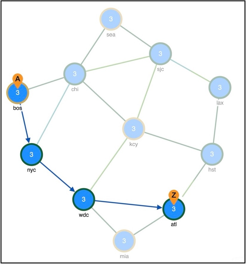
Selected demand paths are shown in blue color. An ā€œAā€ labels the source and a ā€œZā€ labels the destination.

Figure 1. Demand route
Demand route example

Recommendations for demand sources and destinations

Use these recommendations when creating sources and destinations for demand routing:

  • For internal routing, use nodes as sources and destinations.

  • For external ASes, use a combination of ASes, nodes, and interfaces. Specify the exact interface on which the demand traffic enters or exits a node by using interfaces.

  • For complex routing requiring multiple sources, destinations, or failover scenarios, use external endpoints.

  • For multicast routing, use multicast destinations.

If multiple interfaces are attached to a node and a demand is sourced to or destined for that node, traffic splits across one or more of those interfaces, depending on other properties, such as IGP metrics or BGP policies on a peering circuit. You can, however, specify just one of those interfaces.

Note

If using an interface as a source of a demand, it refers to the inbound interface. If using an interface as the destination of a demand, it refers to the outbound interface.


Demand meshes

Demand meshes enable you to create numerous demands efficiently for the entire network. By default, Cisco Crosswork Planning creates a source-destination mesh among nodes, interfaces, external ASes, and external endpoints. There are also advanced options, such as the ability to use a different set of destinations to create the demand meshes.


Demand latency bounds

A demand latency bound is a traffic engineering policy that

  • sets the maximum permissible latency on a demand under normal operation

  • guides route selection of the traffic engineering tools, and

  • helps the Simulation analysis tool determine if latency requirements are violated in worst-case failure scenarios.

Demands table latency measurements

Each demand can have a latency bound. The Demands table provides several Latency columns. Key ones are:

  • Average latency: Average latency over all ECMP subroutes.

  • Minimum latency: Minimum latency over all ECMP subroutes.

  • Maximum latency: Maximum latency over all ECMP subroutes.

  • Min possible latency: Total latency of the shortest path that the demand could take.

  • Diff min possible latency: Maximum latency minus the Minimum possible latency.

  • Latency bound: Maximum permissible latency on a demand.

  • Diff latency bound: Latency bound minus the Maximum latency.