Cisco Crosswork Planning Design 7.2.x User Guide

PDF

Cisco Crosswork Planning Design 7.2.x User Guide

Autobandwidth-enabled LSPs

Want to summarize with AI?

Log in

Introduces autobandwidth-enabled LSP simulations and outlines how convergence behavior changes with traffic levels and failure conditions during RSVP-TE routing analysis.


In a network, autobandwidth-enabled LSPs reset their setup bandwidth periodically based on the configured autobandwidth timers, and establish new routes if necessary. In networks with constrained bandwidth, changes in LSP routes can make other LSPs unroutable, which can then affect the amount of traffic in each LSP, the setup bandwidth settings, and the routes taken, without ever converging.

While Cisco Crosswork Planning does not simulate this instability, it does simulate autobandwidth-enabled LSPs. In this simulation mode, internally Cisco Crosswork Planning first routes the autobandwidth-enabled LSPs with a setup bandwidth of zero. Then, demands are routed to determine the simulated traffic (Traff sim) through each LSP. The result in the plan file and UI is that the Traff sim value is copied to the Setup BW sim for each autobandwidth-enabled LSP, and these LSPs are then routed using their new Setup BW sim value. Note that if some LSPs cannot be routed, the Traff sim and Setup BW sim values resulting from this process might not match one another for all autobandwidth-enabled LSPs.

Autobandwidth simulation modes

There are two autobandwidth simulation modes available. Before simulating failures or running Simulation analysis on autobandwidth-enabled LSPs, choose the appropriate mode depending on which state you need to simulate.

Note
These simulation modes are only available in plan files with a single traffic level.
  • Autobandwidth convergence: In this mode, the network is simulated after the traffic (Traff sim) has been rerouted to other LSPs, but before the Setup BW sim values have been reset. This simulates the immediate, less optimal response to failures.

  • Autobandwidth convergence (including failures): In this mode, the network is simulated after the Setup BW sim values have been reset. This simulates the longer, more optimal response to failures.

These autobandwidth simulations require that the LSPs have their Autobandwidth property set to true, and that one of the two autobandwidth modes be selected from the Network options page (in the toolbar, click or choose Actions > Edit > Network options).
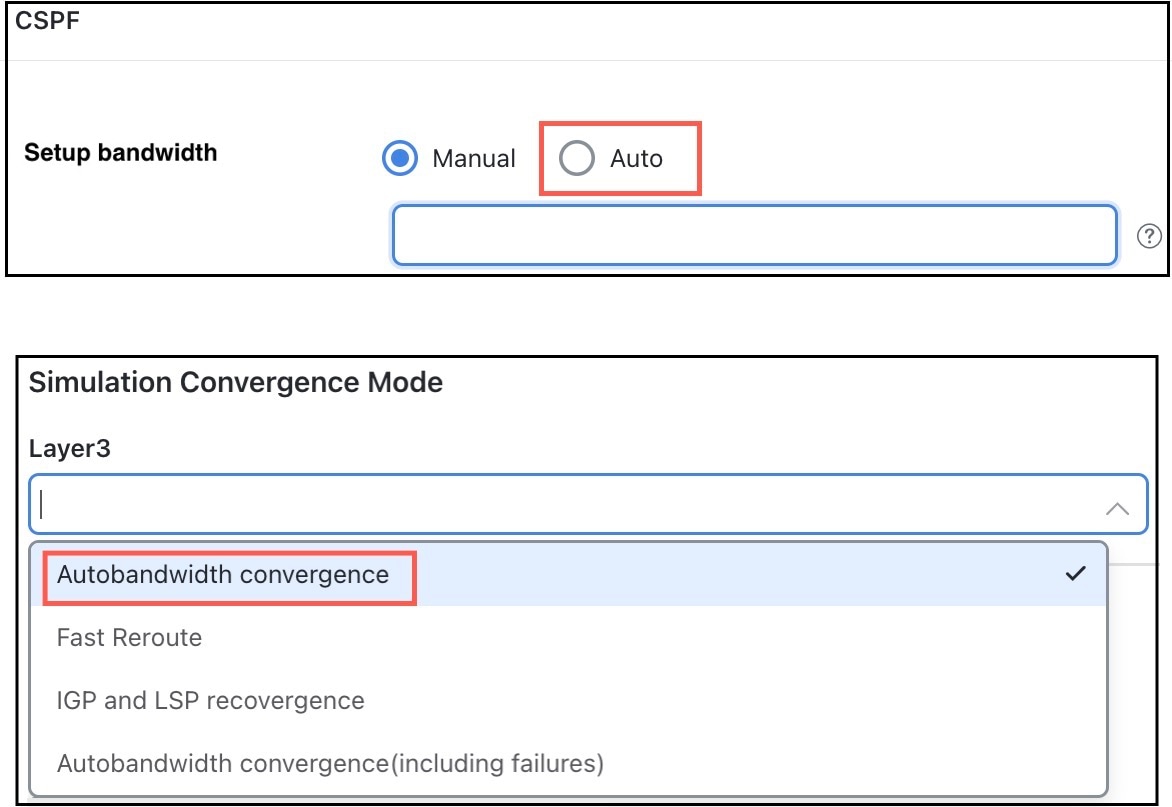
Autobandwidth options

Autobandwidth convergence example with and without failures

This example describes how autobandwidth convergence behaves in a sample MPLS network under normal operation and when failures occur. The scenario highlights key network parameters, routing decisions, and bandwidth allocation across two LSPs.

Network parameters

The network in this example has these parameters:

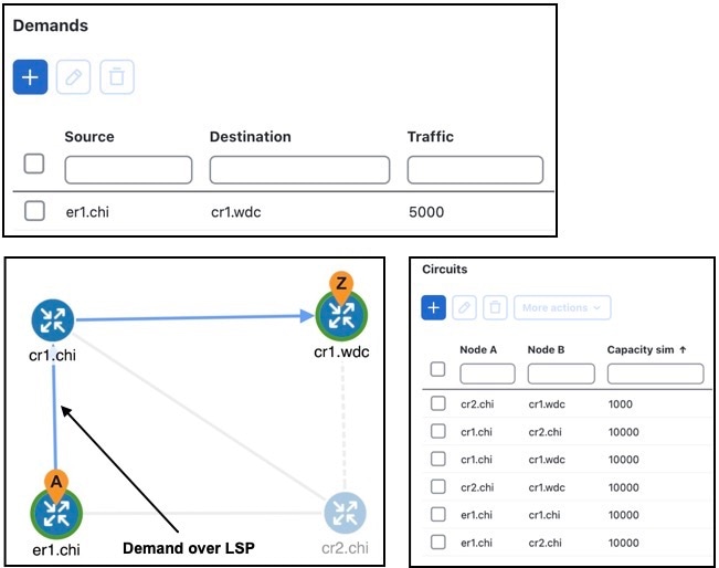
  • Demand: One demand originates from er1.chi and terminates at cr1.wdc.

  • Two LSPs: LSP-A from cr1.chi to cr1.wdc and LSP-B from cr2.chi to cr1.wdc.

  • Setup bandwidth: Neither LSPs has a Setup BW.

  • Circuit capacities: All circuits have a 10,000 Mbps capacity except for one (between cr2.chi and cr1.wdc), which is only 1000 Mbps.

Example network

Scenario comparisons

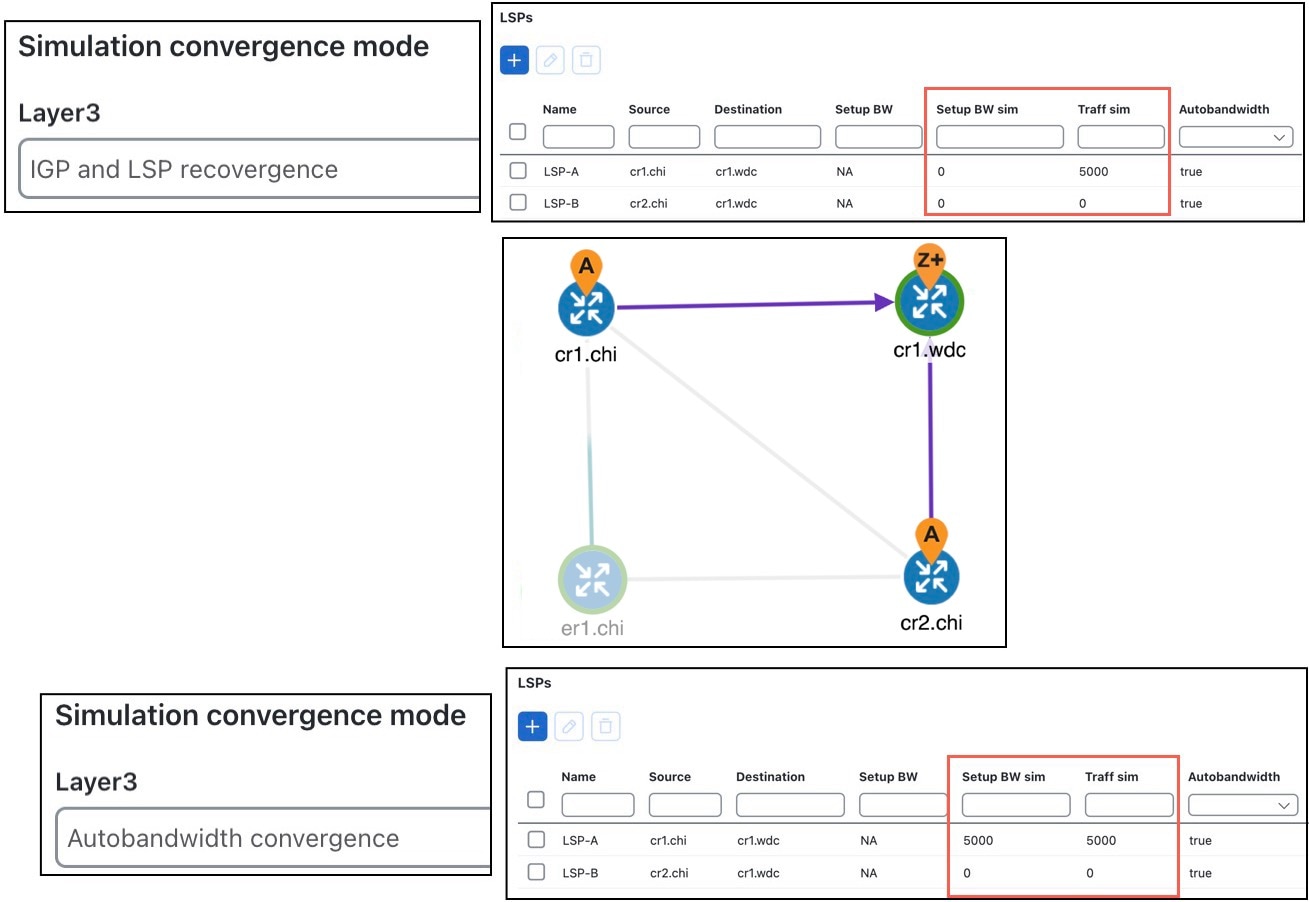
  • Normal operation (no failures) : Example LSP routing using IGP and LSP reconvergence and using autobandwidth convergence shows that in the IGP and LSP Reconvergence mode, the Setup BW sim value for both LSPs is 0.

    • In the Autobandwidth convergence mode, the Setup BW sim value for LSP-A is copied from its Traff sim value, which is 5000.

    • There are no failures, and each LSP follows the same route in both convergence modes.

    Figure 1. Example LSP routing using IGP and LSP reconvergence and using autobandwidth convergence
    LSP routing using IGP and LSP reconvergence and using autobandwidth convergence
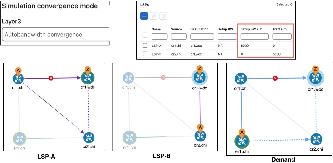
  • Failure event (autobandwidth convergence mode) : Example autobandwidth convergence with failures shows the Autobandwidth convergence mode when there is a failure.

    • Failing the circuit between cr1.chi and cr1.wdc causes LSP-A to reroute through cr2.chi.

    • The shortest path from er1.chi through cr1.chi is now longer than the shortest path from er1.chi through cr2.chi, and so the demand moves over to LSP-B. This is shown in the LSPs table where the traffic (Traff Sim) of LSP-A is moved to LSP-B.

    • Because the smaller of the two circuits is congested, LSP-A uses the larger circuit, which has enough capacity to carry the traffic.

    • LSP-B continues to route on the lower capacity circuit, thus causing congestion.

    • The Setup BW sim value is not updated for either LSP because the Autobandwidth convergence mode does not update setup bandwidth as a result of traffic shifts due to failure.

    Figure 2. Example autobandwidth convergence with failures
    Autobandwidth convergence with failures
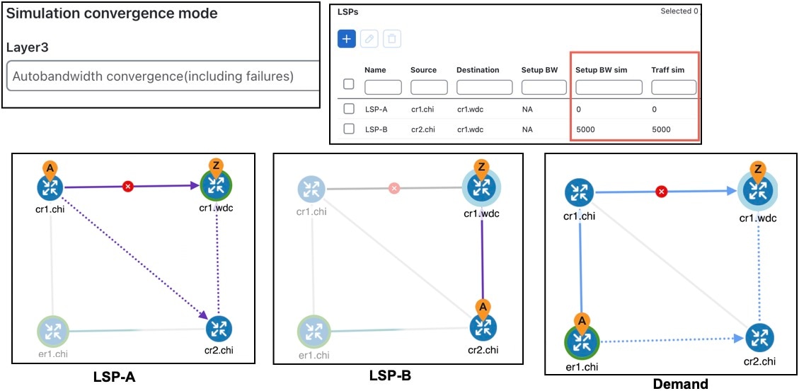
  • Failure event (autobandwidth convergence including failures mode) : Example autobandwidth convergence including failures shows the same failure in Autobandwidth convergence (including failures) mode.

    • The LSP-B Setup BW sim is updated to the Traff sim value, forcing it to take the larger circuit to reach its destination. Note that the plot shows both the normal (solid) and failure (dotted) route for LSP-B, indicating that it has rerouted under the failure, even though the failure did not interrupt its path.

    • The demand continues to route on LSP-B, but because the LSP has found a path with sufficient capacity, there is no more congestion.

    Figure 3. Example autobandwidth convergence including failures
    Autobandwidth convergence including failures