Configure a point-to-point relay topology using two radio interfaces on a single device to establish mesh connectivity.
This task enables you to implement a point-to-point relay topology using two radio interfaces on a single device to establish effective mesh connectivity between mesh points.
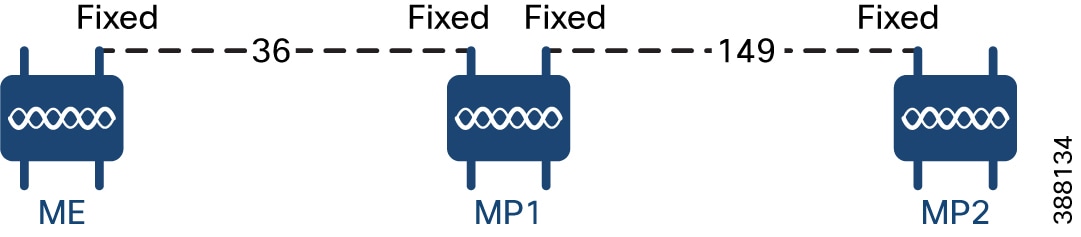
A point-to-point relay topology uses two radio interfaces on a single device (MP1) to establish connectivity. This configuration involves mesh endpoints and mesh points operating on different channels to create the relay connection.
Procedure
| 1. | Configure Mesh End (ME), MP1 on channel 36 and MP2 on the default channel 149. |
|
| 2. | Enable the second slot interface on Mesh Point (MP2) again and wait 30 seconds to implement the point-to-point relay topology for two radio interfaces on a single device. |