Important.
Results generated by AI. Before using results, verify accuracy and completeness.
Copy
Configure ACI border gateway nodes and interfaces to establish eBGP underlay adjacencies with devices in the intersite network.
Before you begin
Register the leaf node with the border-gateway node type so that Cisco APIC identifies it as a VXLAN EVPN border gateway. For more information, see Discover ACI border gateways.
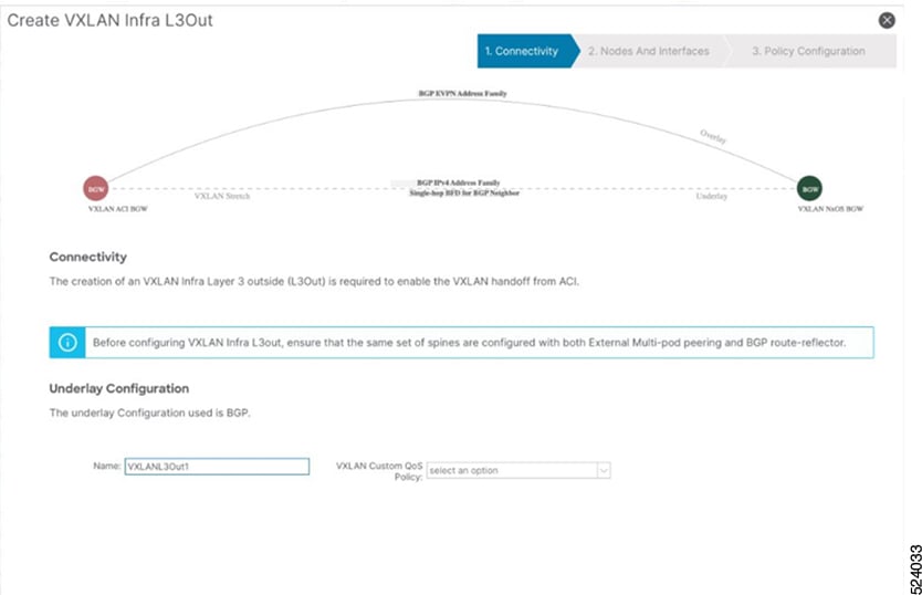
A VXLAN Infra L3Out identifies the ACI border gateway nodes and interfaces that establish eBGP underlay adjacencies with devices in the intersite network (ISN). These adjacencies exchange underlay reachability information with remote Cisco NX-OS border gateways and enable overlay EVPN adjacencies.
Configure the following components for a VXLAN Infra L3Out:
You can configure only border gateway nodes in a VXLAN Infra L3Out.
Each VXLAN Infra L3Out must contain border gateways from multiple pods in the same ACI Multi-Pod fabric.
Based on your QoS policy, you can configure a border gateway in one or more VXLAN Infra L3Outs.
When you configure a node profile, you can configure the router ID and loopback interface for the node. The border gateway uses the IP address assigned to the loopback interface to establish BGP EVPN control-plane peering with Cisco NX-OS border gateways in the remote fabrics.
Interfaces
You can configure a routed interface or subinterface.
Configure the underlay BGP peer policy on the Interfaces tab of the VXLAN Infra L3Out. This configuration establishes the underlay BGP adjacency that advertises the loopback address to the connected device.
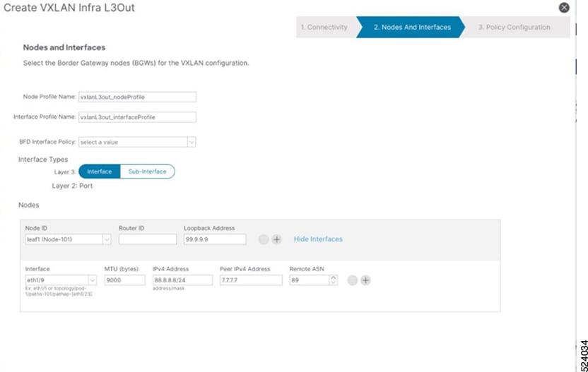
Figure 2. VXLAN Infra L3Out Nodes and Interfaces window
In the Nodes and Interfaces window, configure the border gateway nodes and interfaces:
In the Node Profile Name and Interface Profile Name fields, retain the default profile names or enter different names.
The default node profile name is L3Out-name_nodeProfile, and the default interface profile name is L3Out-name_interfaceProfile. The L3Out-name variable is the name that you entered in the Name field on the Connectivity page.
From the BFD Interface Policy drop-down list, choose an existing BFD interface policy, or choose Create BFD Interface Policy to create a policy.
In the Interface Types area, configure the Layer 3 interface type.
Choose one of the following options:
Interface: Configures a Layer 3 interface between the border gateway switch and the external router.
Sub-Interface: Configures a Layer 3 subinterface between the border gateway switch and the external router.
From the Node ID drop-down list, choose the border gateway node for the VXLAN Infra L3Out.
A warning similar to the following message might appear:
The leaf switch 103 has a Operational Router ID 3.3.3.3 which is used for MP-BGP sessions running between this leaf and spines. User can still configure a different Route ID than 3.3.3.3 but will flap the MP-BGP sessions which are already running on this leaf.
If the node does not have a router ID, continue to 4.e to configure one.
If the node already has a router ID, such as an ID configured for MP-BGP route reflectors, use the same router ID for the VXLAN configuration. You must also use the same router ID for multiple Infra L3Outs. Note the router ID shown in the warning and enter it in 4.e.
In the Router ID field, enter a unique IPv4 router ID for the border gateway switch in the Infra L3Out.
The router ID must be unique across all ACI border gateway switches and non-ACI fabric border gateways.
If the node already has a router ID, as described in 4.d, use the following guidelines:
To use the existing router ID for the VXLAN configuration, enter the router ID displayed in the warning in 4.d.
Use the same router ID for multiple Infra L3Outs.
In the Loopback field, enter the routable control-plane IP address used for EVPN peering.
The underlay protocol advertises this address.
From the Interface drop-down list, choose a port.
If you selected Sub-Interface, enter the encapsulation for the Layer 3 outside profile in the VLAN Encap field.
In the MTU (bytes) field, enter the maximum transmission unit of the external network.
In the IPv4 Address field, enter the IP address for the eBGP underlay configuration.
This address is assigned to the Layer 3 interface or subinterface on the ACI border gateway.
In the Peer IPv4 Address field, enter the IP address of the eBGP underlay unicast peer.
This address is assigned to the interface on the router that is directly connected to the border gateway switch.
In the Remote ASN field, enter the BGP autonomous system number of the directly connected router.
Configure additional interfaces for the node, if required.
To continue without configuring another interface, go to 4.o.
To configure another interface, click + in the Interfaces area and configure the interface.
Note
To remove an interface configuration or an interface row that you added accidentally, click the trash can icon for that row.
Configure additional border gateways for the VXLAN Infra L3Out, if required.
To continue without configuring another border gateway, go to 4.o.
To configure another border gateway, click + in the Nodes area and configure the node.
Note
To remove a node configuration or a node row that you added accidentally, click the trash can icon for that row.
Click Next.
The Policy Configuration window appears.
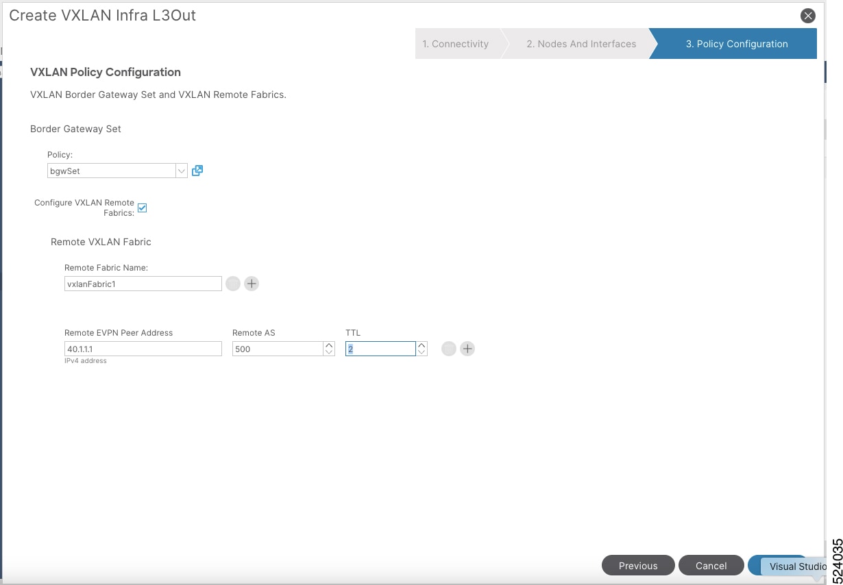
Figure 3. VXLAN Infra L3Out Policy Configuration window
In the Policy Configuration window, configure the border gateway set and remote VXLAN fabrics:
In the Border Gateway Set field, choose an existing border gateway set or create a border gateway set.
Check the Configure VXLAN Remote Fabrics check box and configure the remote fabric:
In the Remote VXLAN Fabric field, choose an existing remote VXLAN fabric, or click + to create one.
In the Remote EVPN Peer Address field, enter the remote EVPN peer address.
This address identifies the remote device with which the local device communicates and establishes the initial connection between the devices. It is also used to route traffic between them.
In the Remote AS field, enter the BGP autonomous system number of the remote Cisco NX-OS border gateway node.
In the TTL field, enter a time-to-live value greater than 1.
Click Finish to complete the configuration in the Create VXLAN Infra L3Out wizard.