Lists the guidelines and limitations for the SR-MPLS handoff feature across supported platforms, configurations, and operational considerations.
This reference provides comprehensive guidelines and limitations for the SR-MPLS handoff feature, including supported platforms, configuration restrictions, routing policy requirements, transit routing capabilities, QoS behavior, and statistics collection considerations.
Supported platforms for SR-MPLS
The SR-MPLS handoff feature is supported on these platforms:
-
Border leaf switches: -FX switch models and later (for example, switch models with "FX", "FX2", "FX3", "GX", and so on at the end of the switch name)
-
Spine switches:
-
Modular spine switch models with "LC-EX", "LC-FX", and "GX" at the end of the linecard name
-
Fixed spine switches Cisco Nexus 9000 series N9K-C9332C and N9K-C9364C
-
-
DC-PE routers:
-
Network Convergence System (NCS) 5500 Series
-
ASR 9000 Series
-
NCS 540 or 560 routers
-
ASR1000/ IOS-XE platforms
-
-
The Cisco Application Centric Infrastructure (ACI)-to-SR-MPLS handoff solution uses a standards-based implementation with SR-MPLS, BGP-LU, BGP EVPN, and prefix re-origination between BGP EVPN and VPNv4/v6. Any DC-PE that supports these technologies should be able to support Cisco ACI to SR-MPLS handoff.
When the Cisco Application Centric Infrastructure (ACI) border leaf switch with the SR-MPLS handoff is connected to a PE device running IOS-XE software, the IOS-XE device should be configured with "neighbor <ACI-leaf> next-hop-unchanged" under the BGP L2VPN EVPN address-family. With next-hop-unchanged configuration, Cisco ACI border leaf switch must learn the remote PE loopback.
Platform limitations for SR-MPLS
-
On the FX platform, enabling the SR-MPLS feature would enable MPLS parsing on all ports, including ports where MPLS is not enabled or deployed. On FX2 platforms and later, MPLS parsing is enabled only on ports where SR-MPLS is enabled or deployed.
-
On ports where MPLS parsing is enabled, pure Layer 2 switching of MPLS encapsulated packets are not supported. Non-MPLS Layer 2 traffic can use the Cisco ACI fabric as Layer 2 transit, without any issues.
-
As SR-MPLS handoff in Cisco ACI is supported only in pipe mode and the TTL value is hardcoded to TTL=32 in the MPLS header for all the data plane packets it may lead to some reachability issues with some cloud hosted SaaS that are more than 32 hops away. The workaround solution would be to disable the TTL propagation on the neighboring router to prevent copy back of the MPLS TTL to the IP header by using this command:
MPLS IP-TTL-propagation disable
Guidelines and limitations for the SR-MPLS infra L3Out
-
Even though a border leaf switch can be in multiple SR-MPLS infra L3Outs, a border leaf switch/provider edge router combination can only be in one SR-MPLS infra L3Out as there can be only one routing policy for a user VRF/border leaf switch/DC-PE combination.
-
If there is a requirement to have SR-MPLS connectivity from multiple pods and remote locations, ensure that you have a different SR-MPLS infra L3Out in each of those pods and remote leaf locations with SR-MPLS connectivity.
-
SR-MPLS infra L3Outs do not support multicast.
Routing Policy
-
Supported: Beginning with Cisco APIC release 6.1(1), fabric ports on a remote leaf can now be deployed on SRMPLS infra l3outs, as a routed sub interface.
Guidelines and limitations for the SR-MPLS VRF L3Out
Routing Policy
-
Within each SR-MPLS VRF L3Out, defining the outbound route map (export routing policy) is mandatory, but defining the inbound route map (import routing policy) is optional.
-
Routing policies associated with any SR-MPLS VRF L3Outs have to be a global type. In other words, you have to explicitly add all the routes, including bridge domain subnets.
-
Host-based routing is not supported with SR-MPLS.
-
Transit routing is supported, but with some restrictions:
-
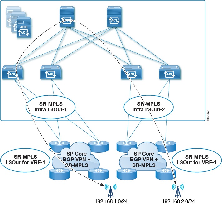
Supported: Transit SR-MPLS traffic with a single VRF using different border leaf pairs, as shown in the following figure. For this configuration, you must advertise the unique prefixes range through each SR-MPLS infra L3out (border leaf pair). You must also ensure that there is no routing loop in the transport network (in other words, that the fabric is acting as a hub with the two-transport network acting as a spoke).
-
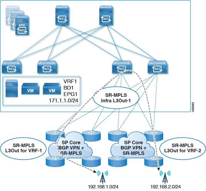
Supported: Transit SR-MPLS traffic with the same border leaf pair and different VRFs, as shown in the following figure.
-
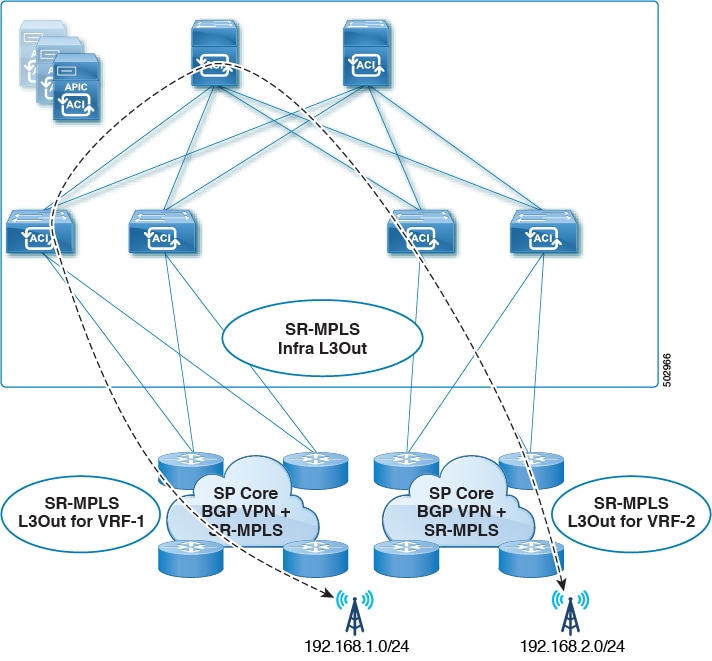
Supported: Transit SR-MPLS traffic with different border leaf pairs and different VRFs, as shown in the following figure.
-
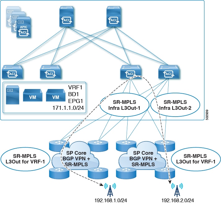
Transit SR-MPLS traffic within the same VRF and on the same border leaf pair, as shown in the following figure:
-
Unsupported for releases prior to Release 5.1(1).
-
Supported for Release 5.1(1) and later, where re-originated routes are prevented from being advertised back into the same Infra L3Out peers to avoid transient loops in the system.
-
-
-
If a leaf switch is configured on multiple SR-MPLS infra L3Outs, the same subnets can be advertised out of all the L3Outs if the prefixes are configured in a single prefix list (in one match rule), and the route map with that prefix list is then associated with all the SR-MPLS VRF L3Outs.
For example, consider this configuration:
-
A single prefix list P1, with subnets S1 and S2
-
SR-MPLS VRF L3Out 1, which is associated with route map R1, with prefix list P1
-
SR-MPLS VRF L3Out 2, which is associated with route map R2, with prefix list P1
Because the prefixes are configured in the same prefix list (P1), even though they are associated with different SR-MPLS VRF L3Outs, the same subnets within prefix list P1 are advertised out of both L3Outs.
On the other hand, consider this configuration:
-
Two prefix lists:
-
Prefix list P1, with subnets S1 and S2
-
Prefix list P2, with subnets S1 and S2
-
-
SR-MPLS VRF L3Out 1, which is associated with route map R1, with prefix list P1
-
SR-MPLS VRF L3Out 2, which is associated with route map R2, with prefix list P2
Because the prefixes are configured in the two prefix lists (P1 and P2), and they are associated with different SR-MPLS VRF L3Outs, subnets S1 and S2 are not advertised out of both of the L3Outs.
-
-
SR-MPLS VRF L3Outs do not support multicast.
Security Policy
-
You can configure a security policy through the external EPG instance profile, which is defined within an SR-MPLS VRF L3Out. The external EPG instance profile contains IP prefixes that are reachable through the SR-MPLS network from one or more SR-MPLS infra L3Outs and need the same security policy.
-
You can configure 0/0 prefix in the external EPG instance profile to classify, as part of the external EPG, the inbound traffic flows originated from any external IP address.
-
You can associate an external EPG in the external EPG instance profile with one or more SR-MPLS VRF L3Outs. When the external EPG instance profile is external to multiple SR-MPLS infra L3Outs, multiple SR-MPLS VRF L3Outs point to the same external EPG instance profile.
-
You must configure contracts between local EPGs and external EPG instance profiles or between external EPGs associated to different VRF L3Outs (to enable transit routing).
Guidelines and limitations for MPLS custom QoS policies
This is the default MPLS QoS behavior:
-
Class of Service (COS) preservation is not supported for intra ToR MPLS egress QoS policies, where the destination port is an MPLS port.
-
All incoming MPLS traffic on the border leaf switch is classified into QoS Level 3 (the default QoS level).
-
The border leaf switch will retain the original DSCP values for traffic coming from SR-MPLS without any remarking.
-
The border leaf switch will forward packets with the default MPLS EXP (0) to the SR-MPLS network.
These are the guidelines and limitations for configuring MPLS Custom QoS policies:
-
Data Plane Policers (DPP) are not supported at the SR-MPLS L3Out.
-
Layer 2 DPP works in the ingress direction on the MPLS interface.
-
Layer 2 DPP works in the egress direction on the MPLS interface in the absence of an egress custom MPLS QoS policy.
-
VRF level policing is not supported.
Guidelines and limitations for SR-MPLS statistics
These are the guidelines and limitations for SR-MPLS statistics:
-
To see the SR-MPLS statistics, you have to perform a one-time stateful reload when enabling the SR-MPLS configuration on any leaf switch.
-
The SR-MPLS interface statistics are only supported only on border leaf switch models with "FX2" or "GX" at the end of the switch name.
-
The SR-MPLS VRF instance statistics are supported on border leaf switch models with "FX," "FX2", or "GX" at the end of the switch name.
-
For the 15 minute historic stats, it might take 20 minutes to update the 15 minute interval data.
-
SR-MPLS interface statistics shown in a switch's CLI get cleared after an admin or operational down event.
-
SR-MPLS interface statistics in a switch's CLI are reported every 10 seconds. If, for example, an interface goes down 3 seconds after the collection of the statistics, the CLI reports only 3 seconds of the statistics and clears all of the other statistics.