Describes the ACI implementation configuration model for SR-MPLS handoff within infra and user tenants. This model facilitates connectivity between the ACI fabric and external devices while enabling policy enforcement.
An SR-MPLS configuration model is an ACI implementation framework that:
-
defines connectivity between the ACI fabric and external devices connected to border leaf switches
-
enables configuration within infra and user tenants to establish SR-MPLS handoff
-
provides route map control for prefix advertisement and security policy enforcement through external EPGs.
Configuration model components
The configuration model includes these components within specific tenants:
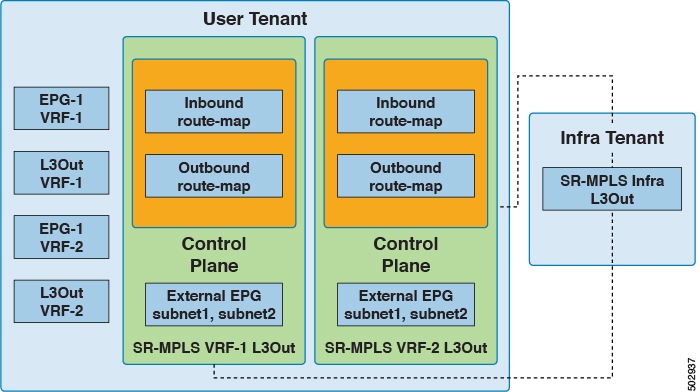
Configuration of SR-MPLS handoff takes place within these tenants:
-
Infra Tenant : Underneath the infra tenant, you will configure the SR-MPLS infra L3Out. The SR-MPLS infra L3Out is where you define the connectivity between the ACI fabric and the external devices connected to the border leaf switches. You will specify the overlay and underlay node path in the SR-MPLS infra L3Out.
-
User Tenant : Underneath the user tenant, you may have multiple VRFs, EPGs, and L3Outs. Within the user tenant, you will configure the SR-MPLS VRF L3Out that you will use as part of the SR-MPLS handoff configuration.
Within the SR-MPLS VRF L3Out, you will also configure these route maps:
-
Inbound route map : By default, the policy for the inbound route map is to accept all prefixes. An explicit inbound route map can be configured to match prefixes or community to selectively deny their advertisement inside the fabric.
-
Outbound route map : You must configure the policy for the outbound route map to advertise any prefix, including bridge domain subnets. By default, the policy for the outbound route map is to not advertise any prefix. An explicit outbound route map can be configured to match prefixes or community to advertise prefixes to the SR-MPLS network and set community, including color community.
Both the inbound route map and the outbound route map are used for the control plane, to set which prefixes are permitted or denied in and out of the fabric.
Within the SR-MPLS VRF L3Out, you will also configure the external EPG and the subnets within this external EPG, which is used for the data plane. These subnets will be used to apply ACI security policies. The external EPG subnet is also used to leak prefixes in another VRF using flags.
-
The external EPG on the SR-MPLS VRF L3Out is not used for routing policies, such as applying a route map to advertise or deny prefix advertisement.
EPG to SR-MPLS L3Out configuration
This example shows an EPG to SR-MPLS L3Out configuration.

In this scenario, you would make these configurations:
-
Configure the SR-MPLS infra L3Out on the border leaf switches (BL1 and BL2 in the figure above)
-
Configure the SR-MPLS VRF L3Out in the user tenant, along with the EPG, bridge domain and user VRFs
-
Configure the route map for exporting and importing on prefixes and apply it to the SR-MPLS VRF L3Out
-
Configure the contract and apply it between the EPG and the external EPG defined on the SR-MPLS VRF L3Out for traffic forwarding between the EPG and the SR-MPLS L3Out
IP L3Out to SR-MPLS L3Out configuration
This example shows a configuration to enable transit routing between a regular IP L3Out and an SR-MPLS L3Out.
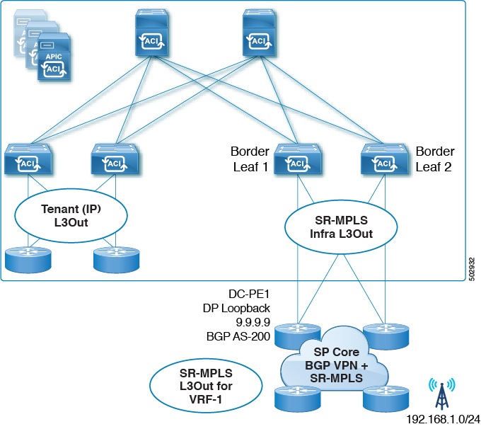
In this scenario, you would make configurations similar to the EPG to SR-MPLS L3Out configuration, with the differences highlighted below:
-
Configure the SR-MPLS infra L3Out on the border leaf switches (BL1 and BL2 in the figure above)
-
Configure the SR-MPLS VRF L3Out in the user tenant, along with the IP L3Out and user VRFs
-
Configure the route map for exporting and importing on prefixes and apply it to the SR-MPLS VRF L3Out
-
Configure the contract and apply it between the external EPGs associated to the IP L3Out and the SR-MPLS VRF L3Out for traffic forwarding between the IP L3Out and the SR-MPLS L3Out