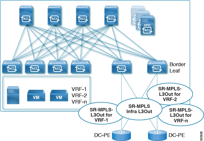
Describes how ACI implements SR-MPLS handoff functionality using specific ACI components that were introduced in Cisco APIC Release 5.0(1).
ACI implements SR-MPLS handoff using the following ACI components that have been introduced in Cisco APIC Release 5.0(1).
SR-MPLS Infra L3Out
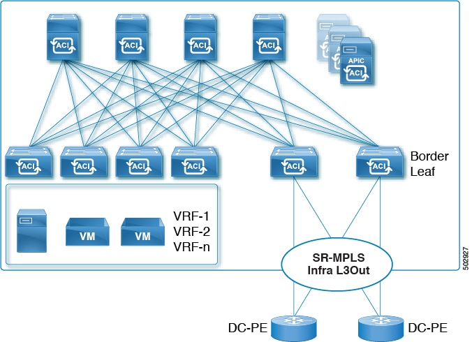
The SR-MPLS infra L3Out provides SR-MPLS connectivity. You will configure the SR-MPLS infra L3Out in the infra tenant on the border leaf switch to set up the underlay MP-BGP EVPN sessions for the SR-MPLS handoff. Tenant VRF instances are selectively mapped to the Cisco Application Centric Infrastructure (ACI) SR-MPLS infra L3Outs to advertise tenant subnets to the DC-PE routers and import MPLS VPN routes from the DC-PE. An SR-MPLS infra L3Out is scoped to a pod or a remote leaf switch site, and is not extended across pods or remote leaf switch pairs.
Figure 1. SR-MPLS Infra L3Out
A pod or remote leaf switch site can have one or more SR-MPLS infra L3Outs.
MP-BGP EVPN Session Between the Cisco ACI Border Leaf Switch and the DC-PE
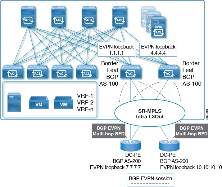
You will need to provide the necessary information to configure the MP-BGP EVPN sessions between the EVPN loopbacks of the border leaf switches and the DC-PE routers to advertise the overlay prefixes, as shown in the following figure.
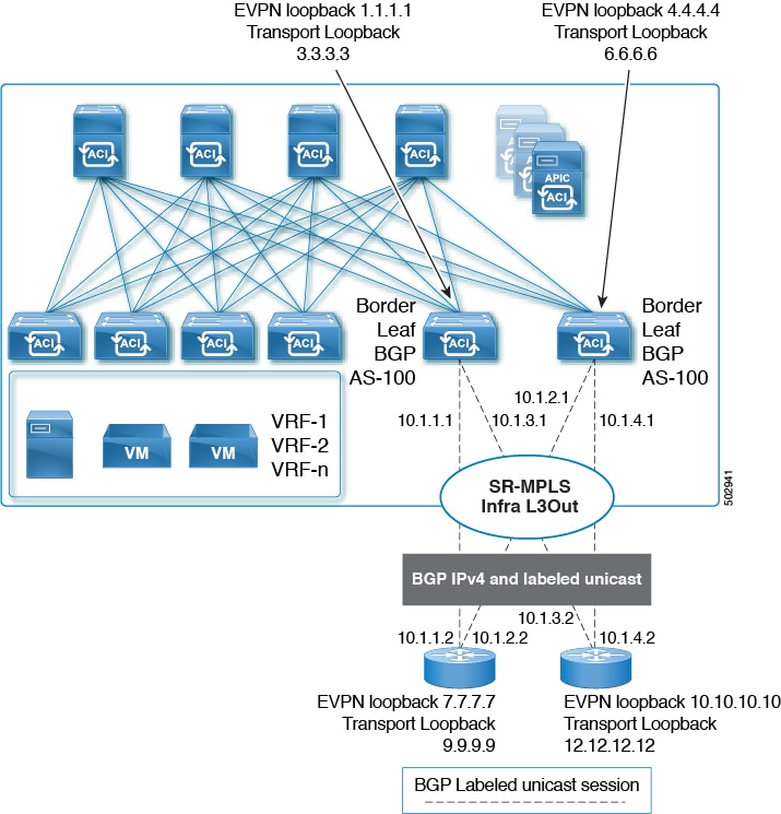
The following configurations take place in this area:
The label advertisement for the transport loopback using the BGP-labeled unicast address family.
A unique router ID on the border leaf switch in the SR-MPLS infra VRF instance.
The router ID should be different from the BGP-EVPN loopback and transport loopback addresses.
While you can use a different IP address for the loopback for the MP-BGP EVPN and the transport as shown in the figure, we recommend that you use the same loopback for the MP-BGP EVPN and the transport loopback on the Cisco ACI border leaf switch.
Only eBGP sessions are supported at this time.
Multi-Hop BFD for BGP EVPN Session
Beginning with release 5.0(1), support is now available for multi-hop BFD, where you can configure multi-hop BFD EVPN sessions between EVPN loopbacks, as shown in the following figure.
A multi-hop BFD with a minimum timer of 250 milliseconds and a detect multiplier of 3 is supported for the BGP EVPN session between the Cisco ACI border leaf switch and the DC-PE. You can modify this timer value based on your requirements.
Underlay BGP Sessions (BGP-Labeled Unicast and IPv4 Address-family) On the Cisco ACI Border Leaf Switch and Next-Hop Router
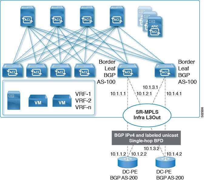
You will also configure the BGP IPv4 and labeled unicast address-family per interface between the Cisco ACI border leaf switches and the DC-PE, as shown in the following figure.
The BGP IPv4 address family automatically advertises the EVPN loopbacks, and the BGP-labeled unicast address family will automatically advertise the SR transport loopback with the SR-MPLS label.
Only eBGP sessions are supported at this time.
Single-Hop BFD for BGP-Labeled Unicast Session
To prevent an issue related to soft failure, where the link remains up but the forwarding capability of the link is impacted, you can configure a single-hop BFD session for the underlay BGP session for the IPv4 and BGP-labeled unicast session, as shown in the following figure.
A single-hop BFD with a minimum timer of 50 milliseconds and a detect multiplier of 3 is supported for the BGP EVPN session between the Cisco ACI border leaf switch and the DC-PE. You can modify this timer value based on your requirements.
You can configure the BFD echo function on one or both ends of a BFD-monitored link. The echo function slows down the required minimum receive interval, based on the configured slow timer. The RequiredMinEchoRx BFD session parameter is set to zero if the echo function is disabled. The slow timer becomes the required minimum receive interval if the echo function is enabled.
SR-MPLS VRF L3Out
An SR-MPLS VRF L3Out is a network configuration component that
associates VRFs with SR-MPLS infra L3Out to advertise prefixes towards SR-MPLS transport
enables configuration of import and export route maps for route policy management, and
supports external EPG configuration with subnets for security policies, PBR policies, and route leaking between VRFs.
SR-MPLS VRF L3Out configuration features
Each VRF, whose prefixes need to be advertised towards an SR-MPLS transport, must be associated with the SR-MPLS infra L3Out. You will configure these associations using the SR-MPLS VRF L3Outs, which are attached to the SR-MPLS infra L3Out.
Figure 2. User tenant SR-MPLS L3Out
You can attach one or more SR-MPLS VRF L3Outs to the same SR-MPLS infra L3Out. Through the SR-MPLS VRF L3Outs, you can configure import and export route maps to do these things:
Apply route policies based on prefixes and/or communities
Advertise prefixes into the SR network
Filter out prefixes received from the SR network
You will also configure an external EPG with one or more subnets on each SR-MPLS VRF L3Out tenant, which is used for these purposes:
SR-MPLS handoff in Cisco ACI is a mechanism that replaces VXLAN encapsulation at the border leaf with MPLS labels to connect the ACI fabric to service provider MPLS or segment routing networks.
In Cisco ACI environments, MPLS TTL handling in SR-MPLS handoff uses a fixed TTL value of 32 in the MPLS header for all data plane packets. Since SR-MPLS handoff in ACI operates in pipe mode, the IP TTL value is not copied into the MPLS header imposed on the packet. Instead, the TTL field in the MPLS header is set to the fixed value of 32. This fixed TTL value may cause packet loss due to TTL expiry if the destination is more than 32 hops away. One workaround is to disable TTL propagation on the neighboring router; however, not all devices support this functionality.
ACI release 6.2(2) introduces a new user-configurable TTL policy that allows setting the TTL value anywhere between 32 and 255. If this policy is not configured, the TTL value defaults to 32.
SR-MPLS custom QoS policies
An SR-MPLS custom QoS policy is a traffic prioritization mechanism that
defines how traffic coming from an MPLS network is prioritized within the ACI fabric
enables re-marking of traffic when it leaves the fabric via an MPLS L3Out, and
applies ingress and egress rules on border leaf switches to classify and mark traffic based on MPLS experimental bits and DSCP values.
Traffic processing rules
When configuring a custom QoS policy, you define two rules that are applied on the border leaf switch:
Ingress rules: Any traffic coming into the border leaf switch connected to the MPLS network will be checked for the MPLS experimental bits (EXP) value and if a match is found, the traffic is classified into an ACI QoS Level and marked with appropriate CoS and differentiated services code point (DSCP) values.
The values are derived at the border leaf using a custom QoS translation policy. The original DSCP values for traffic coming from SR-MPLS are retained without any remarking. If a custom policy is not defined or not matched, the default QoS Level (Level3) is assigned.
Egress rules: When the traffic is leaving the fabric out of the border leaf's MPLS interface, it will be matched based on the DSCP value of the packet and if a match is found, the MPLS EXP and CoS values will be set based on the policy.
If the egress MPLS QoS policy is not configured, the MPLS EXP will default to zero. If they are configured based on the MPLS Custom QoS policy, it will remark the EXP.
These two figures summarize when the ingress and egress rules are applied as well as how the internal ACI traffic may remark the packets' QoS fields while inside the fabric.