This section provides details about automatic power control in Cisco Optical Site Manager. The amplifier software uses a control gain loop to keep channel power constant regardless of the number of channels.
This reference provides information about automatic power control.
The Automatic Power Control (APC) feature performs the following functions:
Maintains constant per-channel power increases optical network resilience, even when changes to the number of channels occur.
Compensates for the degradation of optical networks caused by aging effects.
Simplifies installation and upgrades of DWDM optical networks by automatically calculating amplifier setpoints.
The amplifier software uses a control gain loop to keep channel power constant regardless of the number of channels. It monitors input power changes and adjusts output power proportionately. The shelf controller software emulates the control output power loop to compensate for fiber degradation.
For proper functioning, the control card needs to know the channel distribution via a signaling protocol, and the expected per-channel power which you can set. It compares actual amplifier output power with expected power and adjusts setpoints if needed.
APC at the shelf controller layer
This reference provides information about aPC at the shelf controller layer.
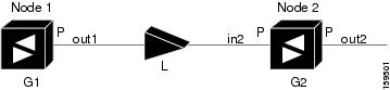
Amplifiers are managed through software to monitor changes in the input power. Changes in the network characteristics have an impact on the amplifier input power. Changes in the input power are compensated for by only modifying the original calculated gain, because input power changes imply changes in the span loss. As a consequence, the gain to span loss established at the amplifier start-up is no longer satisfied, as shown in the following figure.
Figure 1. Using Amplifier Gain Adjustment to Compensate for System Degradation
In the preceding figure, Node 1 and Node 2 are equipped with booster amplifiers and preamplifiers. The input power received at the preamplifier on Node 2 (Pin2) depends on the total power launched by the booster amplifier on Node1, Pout1(n) (where n is the number of channels), and the effect of the span attenuation (L) between the two nodes. Span loss changes due to aging fiber and components or changes in operating conditions. The power into Node 2 is given by the following formula:
Pin2 = LPout1(n)
The phase gain of the preamplifier on Node 2 (GPre-2) is set during provisioning to compensate for the span loss so that the Node 2 preamplifier output power (Pout-Pre-2) is equal to the original transmitted power, as represented in the following formula:
Pout-Pre-2 = L x GPre-2 x Pout1(n)
In cases of system degradation, the power received at Node 2 decreases due to the change of span insertion loss (from L to L'). As a consequence of the preamplifier gain control working mode, the Node 2 preamplifier output power (Pout-Pre-2) also decreases. The goal of APC at the shelf controller layer is simply to detect if an amplifier output change is needed because of changes in the number of channels or to other factors. If factors other than the "changes in the number of channels" factor occur, APC provisions a new gain at the Node 2 preamplifier (GPre-2') to compensate for the new span loss, as shown in the formula:
Generalizing on the preceding relationship, APC is able to compensate for system degradation by adjusting working amplifier gain or variable optical attenuation (VOA) and to eliminate the difference between the power value read by the photodiodes and the expected power value. The expected power values are calculated using:
Provisioned per channel power value
Channel distribution (the number of express, add, and drop channels in the node)
ASE estimation
Channel distribution is determined by the sum of the provisioned and failed channels. Information about provisioned wavelengths is sent to APC on the applicable nodes during the circuit creation. Information about failed channels is collected through a signaling protocol that monitors alarms on ports in the applicable nodes and distributes that information to all the other nodes in the network.
ASE calculations purify the noise from the power level that is reported from the photodiode. Each amplifier can compensate for its own noise, but cascaded amplifiers cannot compensate for ASE generated by preceding nodes. The ASE effect increases when the number of channels decreases; therefore, a correction factor must be calculated in each amplifier of the ring to compensate for ASE build-up.
APC is a network-level feature that is distributed among different nodes. An APC domain is a set of nodes that are regulated by the same instance of APC at the network level. An APC domain optically identifies a network portion that can be independently regulated. Every domain is terminated by two node sides residing on a terminal node, ROADM node, hub node, line termination meshed node, or an XC termination meshed node. An optical network can be divided into several different domains, with the following characteristics:
Every domain is terminated by two node sides. The node sides terminating domains are:
Terminal node (any type)
ROADM node
Hub node
Cross-connect (XC) termination mesh node
Line termination mesh node
APC domains are shown in the GUI.
Inside a domain, the APC algorithm designates a primary node that is responsible for starting APC hourly or every time a new circuit is provisioned or removed. Every time the primary node signals APC to start, gain and VOA setpoints are evaluated on all nodes in the network. If corrections are needed in different nodes, they are always performed sequentially following the optical paths starting from the primary node.
APC corrects the power level only if the variation exceeds the hysteresis thresholds of +/- 0.5 dB. Any power level fluctuation within the threshold range is skipped because it is considered negligible. Because APC is designed to follow slow time events, it skips corrections greater than 3 dB. This is the typical total aging margin that is provisioned during the network design phase. After you provision the first channel or the amplifiers are turned up for the first time, APC does not apply the 3-dB rule. In this case, APC corrects all the power differences to turn up the node.
To avoid large power fluctuations, APC adjusts power levels incrementally. The maximum power correction is +/- 0.5 dB. This is applied to each iteration until the optimal power level is reached. For example, a gain deviation of 2 dB is corrected in four steps. Each of the four steps requires a complete APC check on every node in the APC domain. APC can correct up to a maximum of 3 dB on an hourly basis. If degradation occurs over a longer time period, APC compensates for it by using all margins that you provision during installation.
APC can be manually disabled. In addition, APC automatically disables itself when:
A Hardware Fail (HF) alarm is raised by any card in any of the domain nodes.
A Mismatch Equipment Alarm (MEA) is raised by any card in any of the domain nodes.
An Improper Removal (IMPROPRMVL) alarm is raised by any card in any of the domain nodes.
Gain Degrade (GAIN-HDEG), Power Degrade (OPWR-HDEG), and Power Fail (PWR-FAIL) alarms are raised by the output port of any amplifier card in any of the domain nodes.
A VOA degrade or fail alarm is raised by any of the cards in any of the domain nodes.
The signaling protocol detects that one of the APC instances in any of the domain nodes is no longer reachable.
APC raises the following minor, non-service-affecting alarms:
APC Out of Range-APC cannot assign a new setpoint for a parameter that is allocated to a port because the new setpoint exceeds the parameter range.
APC Correction Skipped-APC skipped a correction to one parameter allocated to a port because the difference between the expected and current values exceeds the +/- 3-dB security range.
APC at the amplifier card level
This reference provides information about aPC at the amplifier card level.
In constant gain mode, the amplifier power out control loop performs the following input and output power calculations, where G represents the gain and t represents time.
Pout (t) = G * Pin (t) (mW)
Pout (t) = G + Pin (t) (dB)
In a power-equalized optical system, the input power scales with the number of channels, and the amplifier software adjusts for power fluctuations caused by changes in the incoming signal's channel count.
The amplifier software detects input power changes at two instances, t1 and t2, as traffic fluctuations occur. In the formula, 'm' and 'n' denote distinct channel numbers, and Pin/ch signifies the input power per channel.
Pin (t1)= nPin/ch
Pin (t2) = mPin/ch
The output power is quickly adjusted in response to input power changes, maintaining constant power for each channel, even during upgrades or fiber cuts, with a reaction time in milliseconds.
The power and mode for each channel are determined by Automatic Node Setup (ANS) on a per-degree basis during provisioning.
Forcing power correction
This reference provides information about forcing power correction.
A wrong use of maintenance procedures can lead the system to raise the APC Correction Skipped alarm. The APC Correction Skipped alarm strongly limits network management (for example, a new circuit cannot be converted into In-Service (IS) state).
The Force Power Correction button in the APC section helps the user to restore normal conditions by clearing the APC Correction Skipped alarm. The use of the Force Power Correction button must be supervised by Cisco TAC to prevent any traffic loss.
Click the Optical Configuration tab and then click APC to expand it.
A list of degrees is displayed.
Select the check box corresponding to the degree you want to enable APC and click the Edit button.
Select automatic-enabled from the Admin Status drop-down list.
Only degrees with Admin Status as force-disabled can be enabled.
Click Apply.
Verify that the Service Status field changes to enabled.
The enable APC task is complete.
Disable APC
Use this task to disable APC.
Use this task to disable APC.
Caution
When APC is disabled, aging compensation is not applied and circuits cannot be activated. Disable APC only to perform specific troubleshooting or node provisioning tasks. When the tasks are completed, enable and run APC. Leaving APC disabled can cause traffic loss.