This chapter covers configuring the node in Cisco Optical Site Manager. Use it to find topics about optical degrees, internal patch cords, and automatic power control.
This chapter describes the tasks related to node configuration in Cisco Optical Site Manager.
If Cisco Optical Site Manager is used to manage an XR device, any configuration changes made to the device using XR (CLI or NETCONF) will trigger a resynchronization of the device in Cisco Optical Site Manager. This means that Cisco Optical Site Manager will temporarily be out of sync with the device while it updates itself with the changes. Any alarms during this period will be reported on Cisco Optical Site Manager after the synchronization process is complete.
Additional information
Removing any line card from the XR device will cause the configuration of the card to revert to the preconfigure state. This will result in the same behavior described above.
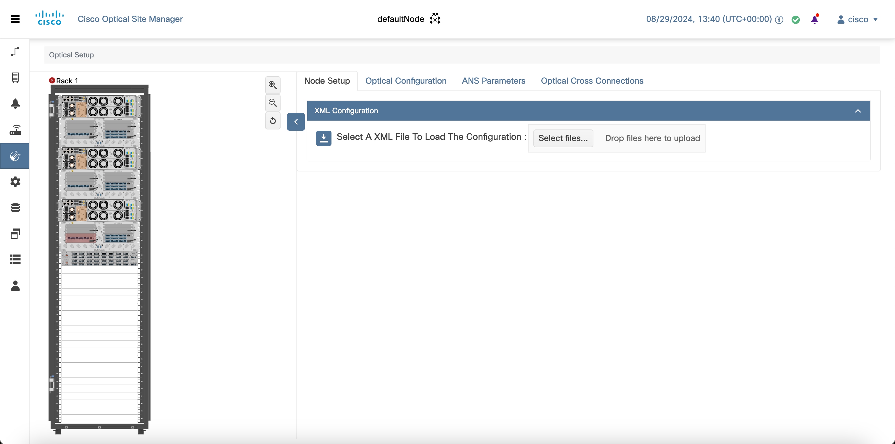
Import a Cisco Optical Network Planner configuration file
Use this procedure to import a Cisco Optical Network Planner configuration file. This task helps you complete the required configuration, verification, or management action in Cisco Optical Site Manager.
Optical degrees
This section explains optical degrees in Cisco Optical Site Manager. From a topological point of view, all the units that are equipped in a node belong to a side.
Internal patch cords
Provides information about internal patch cords in Cisco Optical Site Manager, including virtual links between network termination points and L-band device support considerations.
Automatic power control
This section provides details about automatic power control in Cisco Optical Site Manager. The amplifier software uses a control gain loop to keep channel power constant regardless of the number of channels.
Span loss measurement
This section explains span loss measurement in Cisco Optical Site Manager. Span loss measurements (in dB) check the span loss and are useful whenever changes to the network occur.
Configure amplifier parameters
Use this procedure to configure amplifier parameters in Cisco Optical Site Manager. It helps you complete the required configuration, verification, or management action and confirm the result.
Provision interface parameters
Use this procedure to provision interface parameters. This task helps you complete the required configuration, verification, or management action in Cisco Optical Site Manager.
Provision Raman amplifier parameters
Use this procedure to provision Raman amplifier parameters in Cisco Optical Site Manager. Use it to complete the workflow and verify the result in the related Cisco Optical Site Manager page.
Manage Raman interface parameters
Use this procedure to manage Raman interface parameters in Cisco Optical Site Manager. Use it to complete the workflow and verify the result in the related Cisco Optical Site Manager page.
Optical cross-connect circuits
This section explains optical cross-connect circuits in Cisco Optical Site Manager. It describes key behavior, requirements, and operational context so you can understand when to use the feature.
Submarine Line Terminating Equipment mode
This section explains submarine Line Terminating Equipment mode in Cisco Optical Site Manager. It describes key behavior, requirements, and operational context so you can understand when to use the feature.
GMPLS UNI circuit connections
This section explains GMPLS UNI circuit connections, including how UNI client and network nodes use signaling to establish optical connections and optimize DWDM spectrum usage.
External links
This section explains external links in Cisco Optical Site Manager. In network communication, external links refer to the connections between two optical degrees belonging to adjacent nodes.
Remote node management using GCC
This section explains remote node management using GCC in Cisco Optical Site Manager. The transponder cards that are supported for remote node management using GCC on Cisco web UI are 200G-CK-LC, and 400G-XP and 10x10-LC cards.