Configuration Guide for Cisco Optical Site Manager, IOS XR Release 26.x.x

PDF

Configuration Guide for Cisco Optical Site Manager, IOS XR Release 26.x.x

GMPLS UNI circuit connections

Want to summarize with AI?

Log in

This section explains GMPLS UNI circuit connections, including how UNI client and network nodes use signaling to establish optical connections and optimize DWDM spectrum usage.


A Generalized Multiprotocol Label Switching (GMPLS) User Network Interface (UNI) circuit connection is an optical network connection capability that

  • creates a circuit connection between two UNI-C clients in an optical network,

  • uses signaling exchanges between UNI-C router nodes and UNI-N optical nodes, and

  • enables efficient DWDM spectrum usage for mixed bit-rate or mixed modulation traffic.

Feature history

Table 1. Feature History

Feature Name

Release Information

Description

GMPLS UNI Circuit Connection

Cisco IOS XR Release 25.1.1

You can now establish circuit connections between two clients within an optical network using the Generalized Multiprotocol Label Switching (GMPLS) User Network Interface (UNI). This connection is facilitated through signaling exchanges between UNI Client (UNI-C) nodes, which are router nodes, and UNI Network (UNI-N) nodes, which are optical nodes.

This integration enables effective usage of the DWDM grid with minimal wastage of spectral bandwidth and allows the transmission of mixed bit-rate or mixed modulation data in a grid with different channel widths.

GMPLS UNI details

The Generalized Multiprotocol Label Switching (GMPLS) User Network Interface (UNI) creates a circuit connection between two clients (UNI-C) of an optical network.

GMPLS UNI Advantages

GMPLS UNI plays a crucial role in connecting and optimizing network functionalities:

  • GMPLS UNI allows packet networks to directly access the optical transport control plane, enabling coordination of resource requirements with the optical transport network.

  • By leveraging open standards, GMPLS UNI optimizes network resources and enhances utilization across both packet and optical networks.

Channel Spacing Types in GMPLS

GMPLS supports two types of channel spacing, each affecting the capacity and flexibility of traffic management:

  • Fixed Grid Channel Spacing: This spacing is fixed at 50 GHz, supporting traffic rates of 100 and 200 Gbps.

  • Flexible Grid Channel Spacing: This spacing is set at 6.25 GHz, accommodating all data rates.
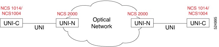

Create a GMPLS UNI tunnel

Use this task to establish a GMPLS UNI tunnel by preparing the node, patch cord, LMP, and optical cross-connection configuration at each endpoint.

Figure 1. GMPLS UNI Tunnel Between two NCS 1014/NCS 1004 Nodes

Creating a tunnel between two NCS 1014 or NCS 1004 nodes on a network involves establishing a connection from the headend to the tailend. The tunnel can be created between the source and destination NCS 1014 or NCS 1004 nodes without involving NCS 2000 nodes in the middle. The NCS 2000 provides GMPLS control plane support and enables dynamic provisioning and rerouting of lightpaths.

These stages describe how to create a connection between the NCS 1014 and NCS 2000 at the headend of the network.

Repeat the same steps at the tailend of the network to ensure complete connectivity.

Before you begin

  • The NCS 2000 node must possess a valid license for ROADM and WSON support.

  • Management IP addresses for both NCS 1014/NCS 1004 and NCS 2000 nodes must be accessible.

  • The administrative state of the trunk port of the optics controller on the NCS 1014 or NCS 1004 node must not be in the shutdown state.

Follow these steps to create a GMPLS UNI tunnel.

Procedure

  1. Add a card mode on the NCS 1014 or NCS 1004 card. For more details, see Add card mode for NCS 1000 cards.

  2. Add internal patch cords between the NCS 1014 or NCS 1004 and NCS 2000 ports. For details, see Create internal patch cords.

  3. Create a static Link Management Protocol link to establish connectivity between a NCS 2000 node and a NCS 1014 or NCS 1004 node. For details, see Create a static Link Management Protocol link for GMPLS.

  4. Create optical cross connections using Cisco Optical Network Controller. For details, see Create Optical Cross Connections.

  5. Repeat the same steps at the tailend of the network to ensure complete connectivity.

The GMPLS UNI tunnel is prepared at the headend and tailend of the network.


Before you begin

Follow these steps to create a static Link Management Protocol link for GMPLS.


Select the LMP type

Use this procedure to select the LMP type in the Cisco Optical Site Manager LMP Configuration Wizard. The selected type determines the supported endpoint and optical parameter options.

The LMP Type area in the Cisco Optical Site Manager LMP Configuration Wizard allows users to choose from various LMP Types.

Use this task to enter the LMP Configuration Wizard and select a card mode.

Before you begin

Log into Cisco Optical Site Manager

Follow these steps to select the LMP type.

Procedure

  1. Click Optical Setup in the left panel.

  2. Click the Optical Configuration tab and then click GMPLS > LMP to expand it.

  3. Click the + button to open LMP Configuration Wizard.

    1. From the LMP Type drop-down list, choose the type of LMP.

    If the LMP link is going to be established with

    Select...

    NCS 1004 or 1014 device

    LOCAL TXP/OCHNC

    NCS 1004 or NCS 4000 routers

    Signaled

    a TXP in a remote NCS 2000 ROADM node

    Remote TXP

    Note

    The LOCAL TXP/OCHNC and Remote TXP systems support a multi-carrier configuration, which involves bundling two Add & Drop ports to enable inverse multiplexing of traffic across trunks. This approach optimizes bandwidth distribution. However, the Signaled LMP does not support multi-carrier configuration.

  4. Click Next.


Configure LMP optical parameters

Use this procedure to configure optical parameters for an LMP link. Configure values such as TXP controller mode, Alien ID, trunk mode, FEC mode, channel mode, and remote node settings.

Use this task to configure various optical parameters for different LMP types:

Before you begin

Select the LMP type

Follow these steps to configure LMP optical parameters.

Procedure

  1. Enter a name for the LMP in the Description field.

    NCS 1014 does not support GMPLS-UNI.

  2. Choose the TXP Controller Mode.

    This field is available only for Local TXP/ OCHNC LMP type. The available options are:

    TXP mode

    Applicable for

    RSVP (GMPLS)

    NCS 1004

    Local

    NCS 1004

    Controller

    NCS 1014

  3. Choose the Alien ID, Trunk Mode, and FEC Mode. See LMP Alien ID FEC and trunk modes for the list of aline ids and its corresponding trunk modes and FEC modes.

    This field is available only for Local TXP/ OCHNC LMP type, and Signaled LMP type with Add/Drop End-Point Type.

  4. Choose the UNI Control Mode as UNI-Clinet or UNI-Netwrok.

    This field is available only for Signaled LMP type.

  5. Select the Channel Mode as Flex or DWDM.

  6. If required, enter the Remote Node Address and Remote IF Index.

  7. Check the Is Local checkbox, to configure the UNI parameters on the client port of the TXP card

    This check-box is available only for Signaled LMP type.

  8. Click Next.


Select LMP end points

Use this procedure to select LMP end points in Cisco Optical Site Manager. Select the ingress and egress chassis, passive unit, slot, port, and remote description details.

Use this task to select the end points for the LMP:

Before you begin

Configure LMP optical parameters

Follow these steps to select LMP end points.

Procedure

  1. In the Ingress Port Selection and Egress Port Selection areas:

    1. From the Type drop-down list, select Chassis, Passive Unit, or Passive Chassis.
    2. From the UID drop-down list, select the UID.
    3. From the Slot drop-down list, select the slot.
    4. From the Port drop-down list, select the port.
    5. Enter a name in the Remote Description field.
  2. Click Next.

What to do next

Verify LMP configurations.


Verify LMP configurations

Use this procedure to verify LMP configurations before completing the wizard. Review the type, optical parameters, and end point selections, and then finish the LMP configuration.

In the Configuration Recap window, verify the selected configurations across the various windows of the LMP Configuration Wizard.

Before you begin

Select LMP end points

Follow these steps to verify LMP configurations.

Procedure

  1. Click to expand the Type, Optical Parameters, and End Points sections to verify the configured details.

  2. Click Finish to complete the LMP configuration.

What to do next

Create an LMP regeneration pair.

Create an LMP regeneration pair

Use this procedure to create an LMP regeneration pair for longer links. Select the required RSVP LMPs and create the regeneration path from the LMP Regen tab.

You can create regeneration pair to create a regeneration path for longer link. Use this task to create a regeneration pair.

Before you begin

Create the required number of LMP links using these tasks:

Follow these steps to create an LMP regeneration pair.

Procedure

  1. Select the LMPs to be added to the regeneration path.

    Note

    You can add only the RSVP type of LMPs into the pair.

  2. Click Regen Pair.

    The regen pair gets created and you can view the same under the LMP Regen tab.


LMP Alien ID FEC and trunk modes

Review details about LMP Alien ID support, including the optical interfaces, trunk modes, and FEC modes available for LMP configuration.

This table lists the optical interfaces (Alien IDs) supported for all LMP types, along with their corresponding trunk modes and FEC modes.

Table 3. Alien IDs supported for LMP

Alien ID

Trunk Mode

FEC Modes

100G-LC-C

Default-Mode

STANDARD_FEC, HG_FEC_7, SD_FEC_20

100G-CK-C

Default-Mode

STANDARD_FEC, HG_FEC_7, SD_FEC_20

200G-CK-LC

100G-Mode

STANDARD_FEC, HG_FEC_7, SD_FEC_20

200G-Mode

SD_FEC_20

100GS-CK-LC

100G-Mode

STANDARD_FEC, HG_FEC_7, SD_FEC_20

200G-Mode

SD_FEC_20

400G-XP-LC-CFP2

100G-Mode

SD_FEC_15_DE_ON, SD_FEC_15_DE_OFF, SD_FEC_25_DE_ON, SD_FEC_25_DE_OFF

150G-Mode

SD_FEC_15_DE_ON, SD_FEC_15_DE_OFF, SD_FEC_25_DE_ON, SD_FEC_25_DE_OFF

200G-Mode

SD_FEC_15_DE_ON, SD_FEC_15_DE_OFF, SD_FEC_25_DE_ON, SD_FEC_25_DE_OFF

NCS10x4 (NCS1K4-1.2T-K9, NCS1K4-2-QDD-C-K9)

200G-Mode

SD_FEC_27

200G-2dot3125-BPS-Mode

SD_FEC_27

300G-3-BPS-Mode

SD_FEC_27

300G-3dot4375-BPS-Mode

SD_FEC_27

400G-Mode

SD_FEC_27

400G-4dot4375-BPS-Mode

SD_FEC_27

500G-Mode

SD_FEC_27

600G-Mode

SD_FEC_27

ONS-CFP2D-400G-C-FOIC(NCS1K4-OTN-XP)

400G-Mode

OFEC

300G-Mode

OFEC

200G-4-BPS-Mode

OFEC

200G-2-BPS-Mode

OFEC

200G-3-BPS-1-E-Mode

OFEC

200G-4-BPS-1-E-Mode

OFEC

100G-1-S-Mode

OFEC

DP04QSDD

100G-Mode

OFEC

200G-Mode

OFEC

200G-4-BPS-Mode

OFEC

200G-6-BPS-Mode

OFEC

200G-8-BPS-Mode

OFEC

200G-0-S-Mode

OFEC

300G-0-S-Mode

OFEC

400G-0-S-Mode

OFEC

NCS1K(NCS1002-K9)

100G-Mode

STANDARD_FEC, HG_FEC_7, SD_FEC_20

DCO-CFP2-8QAM-200G

200G-Mode

SD_FEC_15_DE_ON

QSFP-DD-ZR

400G-Mode

CFEC

QSFP-DD-ZR+

100G-Mode

OFEC

300G-Mode

OFEC

200G-4-BPS-Mode

OFEC

200G-6-BPS-Mode

OFEC

200G-8-BPS-Mode

OFEC

200G-0-S-Mode

OFEC

300G-0-S-Mode

OFEC

400G-Mode

CFEC, OFEC

400G-0-S-Mode

OFEC

ONS-CFP2D-400G-C (NCS1K4-1.2T-MXP)

100G-Mode

OFEC

300G-Mode

OFEC

200G-4-BPS-Mode

OFEC

200G-6-BPS-Mode

OFEC

200G-8-BPS-Mode

OFEC

200G-0-S-Mode

OFEC

300G-0-S-Mode

OFEC

400G-Mode

OFEC

400G-0-S-Mode

OFEC

  • CIM8-C-K9

  • CIM8-CE-K9

  • CIM8-LE-K9

  • 400G-Mode

  • 500G-Mode

  • 600G-Mode

  • 700G-Mode

  • 800G-Mode

  • 900G-Mode

  • 1000G-Mode

  • 1100G-Mode

  • 1200G-Mode

SD_FEC_15