Configuration Guide for Cisco Optical Site Manager, IOS XR Release 26.x.x

PDF

Configuration Guide for Cisco Optical Site Manager, IOS XR Release 26.x.x

Configuring card modes for NCS 2000 line cards

Want to summarize with AI?

Log in

This section describes how configuring card modes for NCS 2000 line cards works in Cisco Optical Site Manager. It explains the sequence, context, and expected outcome of the related workflow.


You can configure NCS 2000 line cards in various operational modes, such as Muxponder and Slice configurations. These modes determine how the line card processes data and manages traffic, enabling efficient client-to-trunk mapping.

Summary

Configuring card modes for NCS 2000 line cards enables optimized data processing and traffic management by selecting the operational mode and setting relevant parameters.

  • NCS 2000 line card: Provides multiple operational modes such as Muxponder and Slice to manage client-to-trunk mapping.

  • Card Configuration Wizard: A tool within Cisco Optical Site Manager that guides the user through the configuration steps.

  • Cisco Optical Site Manager: The management interface where the configuration workflow is executed.

For details about the supported card modes for Cisco NCS 2000 cards, including peer-card requirements and client-to-trunk port mappings, see Supported operating modes and port mapping details for NCS 2000 cards.

Note

When configuring the MXP-4x100G-TXP-400G or 10G-Grey-MXP operation modes on an OTN-XP card via Cisco Optical Site Manager (COSM), consider these synchronization behaviors:

  • Partial configuration (Mode only): If you apply the operation mode without defining the associated slice, trunk, or client configurations, the mode will be applied to both COSM and IOS-XR. However, if you later delete this mode from COSM, it will be removed from the COSM interface but will remain in the IOS-XR configuration, resulting in a synchronization discrepancy.

  • Full configuration (Mode + Slice/Trunk/Client): If you configure the operation mode alongside its required slice, trunk, and client settings, the deletion process will correctly propagate, removing the configuration from both COSM and IOS-XR.

To maintain configuration integrity and prevent orphaned settings on your device, always include the necessary slice, trunk, and client configurations when setting these operation modes in Cisco Optical Site Manager.

Workflow

The process involves these stages:

  1. Select the required card mode for the NCS 2000 line card. For details, see Select a card mode for an NCS 2000 line card.

  2. Add secondary modules for the selected card mode. For details, see Add secondary modules.

  3. Add pluggable modules to the required ports. For details, see Add pluggable modules to ports.

  4. Verify configuration details and complete the wizard. For details, see Verify card configuration details.

Result

The line card is configured in the selected operational mode.

Select a card mode for an NCS 2000 line card

Set the operational behavior for an NCS 2000 line card. Choose the card mode that matches your deployment requirement.
Table 1. Feature History

Feature Name

Release Information

Feature Description

Peer card support for 15454-M-10x10G-LC line card

NCS 2000 Release 26.1.1

The 15454-M-10x10G-LC line card now supports enhanced interoperability, allowing it to function as a peer card for the 15454-M-100G-LC-C or interwork with the 400G-XP-LC.

  • 15454-M-100G-LC-C Pairing: By utilizing the MXP-10x10G operation mode, the 15454-M-10x10G-LC supports a variety of client pluggable ports, including 10GE, OTU2/e, and OC192/STM64.
  • 400G-XP-LC Interworking: The 400G-XP-LC card can now peer with one or more 10x10G-LC cards through a CXP interface and a CXP 24-2x12 MPO breakout cable. In this configuration, ensure the OCH-CC is created up to the 400G-XP-LC client port.

This functionality allows network operators to increase port density, optimize slot utilization, and streamline the deployment of high-capacity muxponder services.

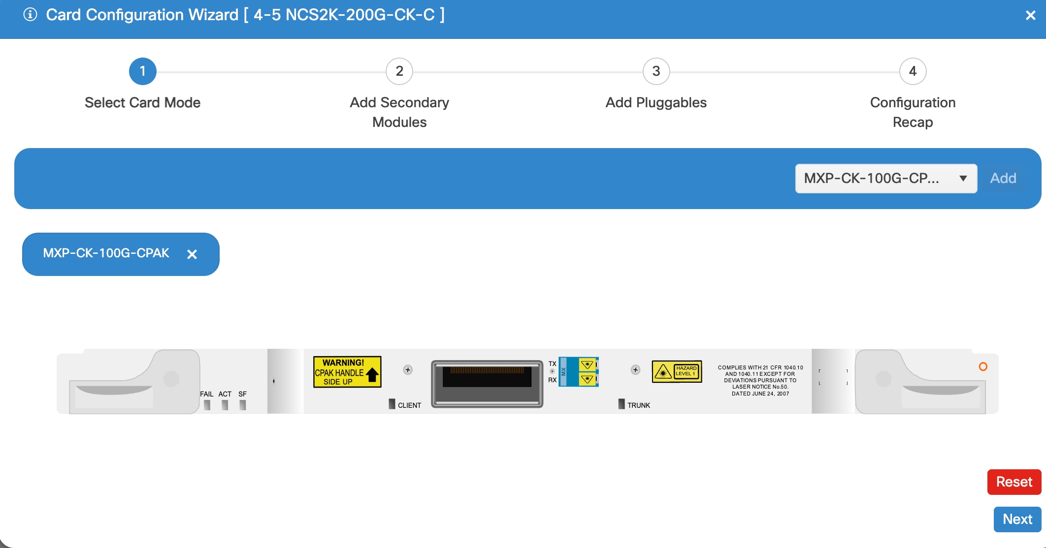
The Card Configuration Wizard in Cisco Optical Site Manager provides an interface for selecting card modes. The selected card mode determines which functions and capabilities are enabled for the line card.
Figure 1. Select card mode

From Release 26.1.1, you can configure the 15454-M-10x10G-LC line card as a peer card for the 15454-M-100G-LC-C and 400G-XP-LC cards.

These client ports are supported for these configurations:

  • 10GE

  • OTU2/e

  • OC192/STM64

The peer and main card combinations are supported in these slot pairs:

  • 2 and 3

  • 4 and 5

  • 6 and 7

  • 8 and 9

  • 10 and11

  • 12 and 13

  • 14 and 15

Before you begin

Log into Cisco Optical Site Manager

Follow these steps to open the Card Configuration Wizard and select a card mode for an NCS 2000 line card.

Procedure

  1. Open the Card Configuration Wizard in one of these ways.

    From rack or card view

    From the tabbed view

    1. Right-click a line card.

    2. Click Card Mode.

    3. Select Install.

    1. Click the Provisioning tab.

    2. Click the Card Modes section to expand it.

    3. Click the Add Card mode button.

  2. From the drop-down list, select the card mode, and then click Add.

    To enable the 15454-M-100G-LC-C card and 400G-XP-LC card as peer card for the 15454-M-10x10G-LC line card, select these modes:

    For 15454-M-100G-LC-C pairing, select MXP-10x10G muxponder mode for the 15454-M-10x10G-LC.

    For 400G-XP-LC pairing, select the MXP mode along with OPM-PEER-ODU2 or OPM-PEER-ODU2e sub-modes for the 15454-M-10x10G-LC

  3. Click Next.

What to do next

Add secondary modules


Add secondary modules

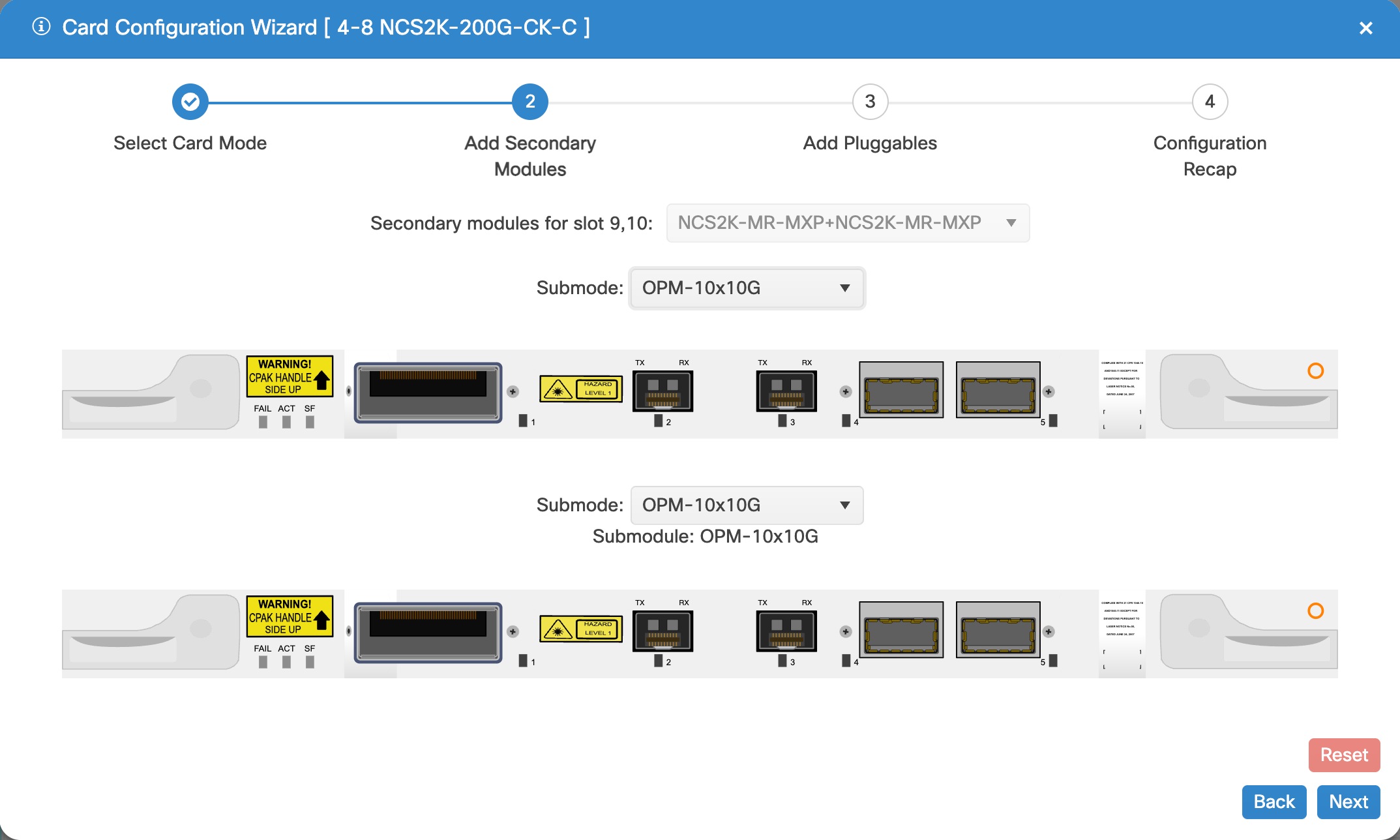
Use this task to add a secondary module in the Card Configuration Wizard for the selected card mode. A secondary module is an add-on hardware module for the NCS 2000 line card that expands interface capacity based on the selected card mode.

Figure 2. Add secondary modules

Before you begin

Select a card mode for an NCS 2000 line card

Follow these steps to add a secondary module for an NCS 2000 line card:

Procedure

  1. From the Secondary modules for slot drop-down list, select the required secondary module.

    This drop-down list is only enabled if the supported secondary modules are available for the card.

  2. Select a submode for all slots from the Submode drop-down list.

    This drop-down list is enabled only when the supported sub modes are available for the card.

  3. Click Next.

The selected secondary module is added.

What to do next

Add pluggable modules to ports


Add pluggable modules to ports

Add pluggable modules to the required ports to expand or update the card capabilities.

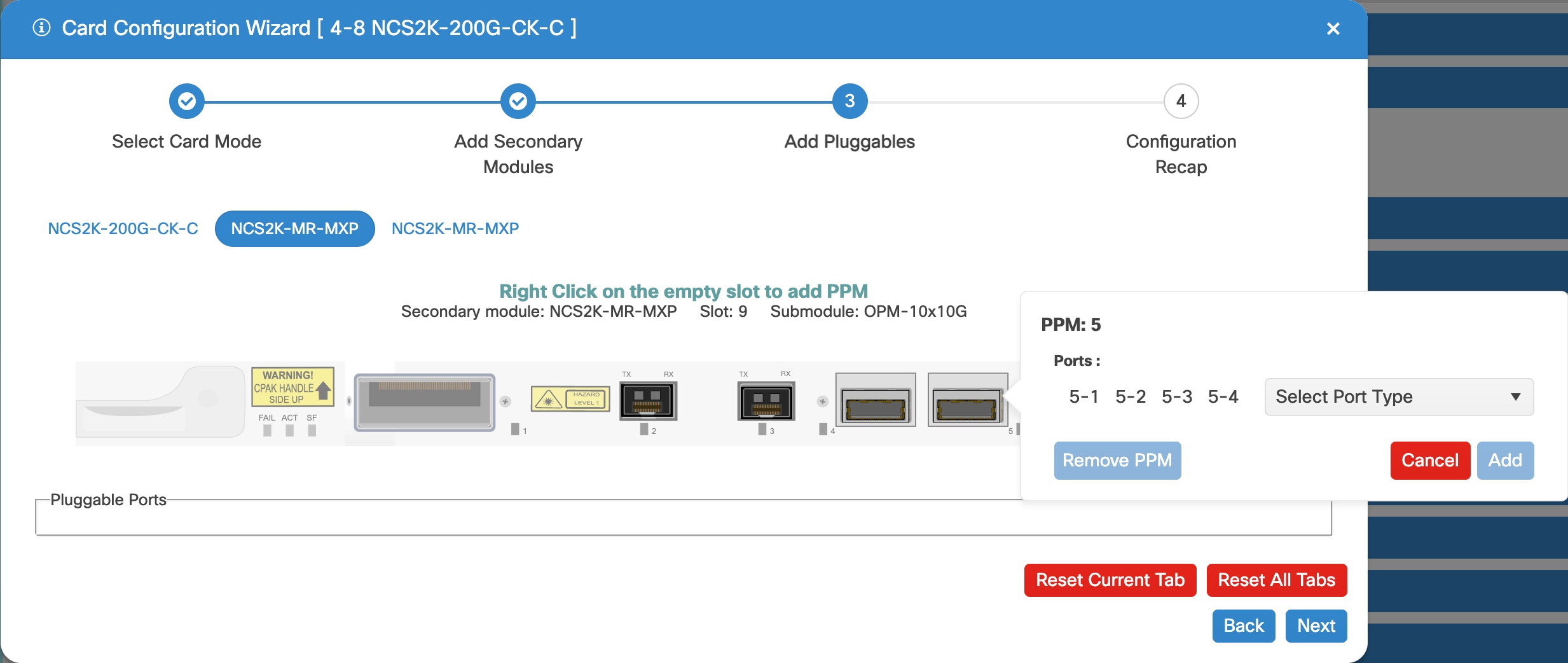
Use the Card Configuration Wizard to assign or remove pluggable modules (PPMs) on specific ports during the card setup or modification process.
Figure 3. Add pluggable modules

Before you begin

Add secondary modules

Procedure

  1. Right-click a port and select the PPM from the Select Port Type drop-down list.

  2. Click Add to assign the PPM to the selected port.

  3. If you need to remove a module, click Remove PPM.

  4. Repeat steps 1 through 3 for each port you want to configure.

  5. Click Next.

The selected pluggable modules are added to the ports.

What to do next

Verify card configuration details


Verify card configuration details

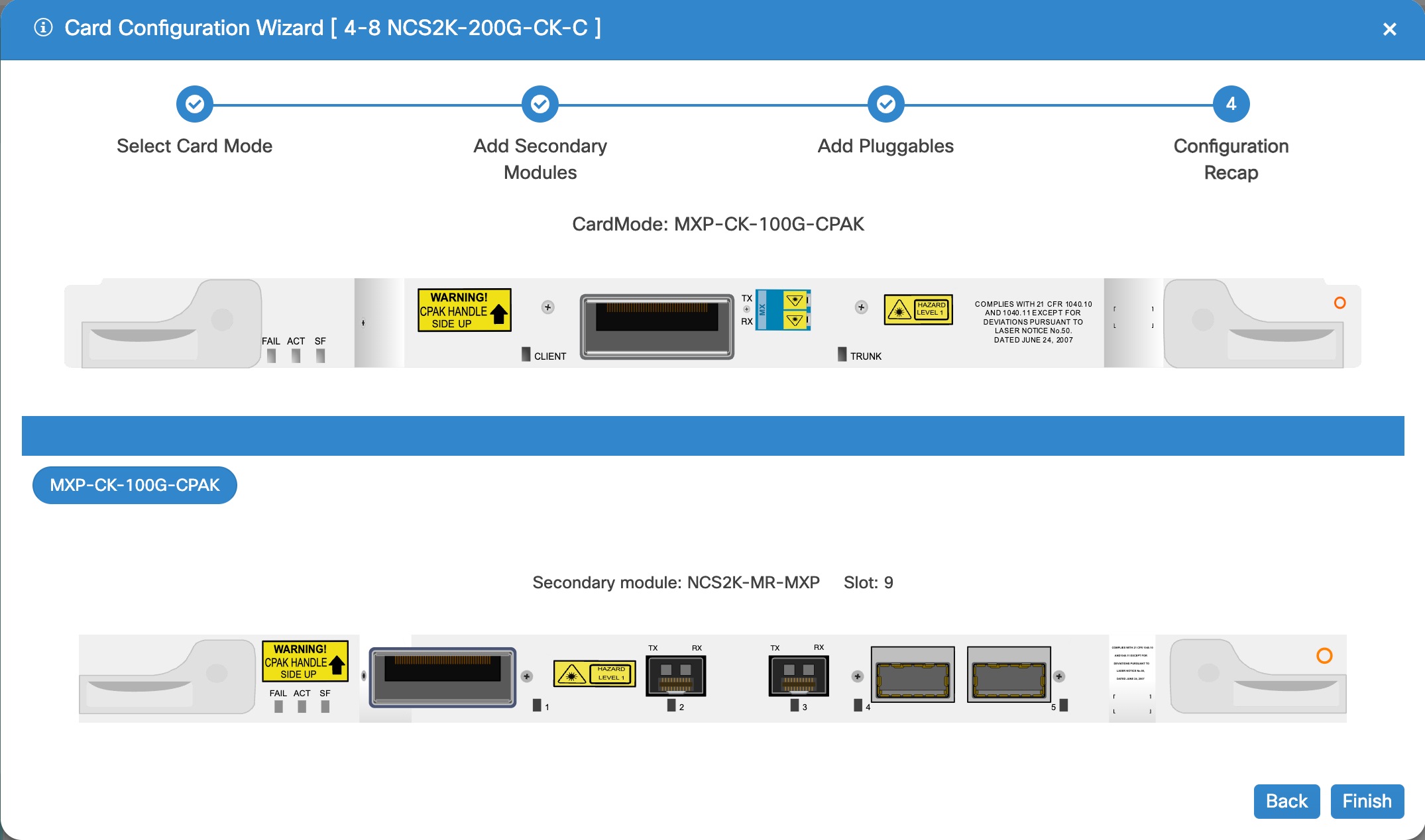
Ensure that the card configuration, including card mode, secondary modules, and port module assignments, is correct before completing the wizard.

In the Card Configuration Wizard, verify the configuration in the Configuration Recap window.

Figure 4. Verify configuration details

Before you begin

Add pluggable modules to ports

Follow these steps to verify card configuration details and complete the Card Configuration Wizard:

Procedure

  1. Verify the card mode displayed in the Configuration Recap window.

  2. Verify secondary modules and slot details.

  3. To verify the PPM and pluggable port assignments, expand the Pluggable Port Modules and Pluggable Ports.

  4. Click Finish.

The system saves the card configuration with the verified settings.


Configure card mode on a NCS 2000 control card

Add a card mode to an NCS 2000 controller card in Cisco Optical Site Manager to enable switching between supported control card modes.

Control cards support multiple card modes that determine how the card processes payloads.

You can configure the operating mode based on the type of control card installed in the shelf.

  • TNC is the default operating mode.

  • TNCO mode is required when a TNCS-O card is installed.

Before you begin

Follow these steps to provision an operating mode on a control card.

Procedure

  1. Click the Provisioning, then click Card Modes tabs.

  2. Select TNC-MODE or TNCO-MODE, then click Apply.

    The control card can operate in either TNC or TNCO mode.

    • TNC mode is the default operating mode.

    • TNCO mode is required when a TNCS-O card is installed.

The operating mode is provisioned on the control card.


Supported operating modes and port mapping details for NCS 2000 cards

Use this reference to identify supported operating modes, valid peer-card combinations, and port mapping details for Cisco NCS 2000 cards before configuring card modes in Cisco Optical Site Manager.

Supported card modes for NCS 2000 cards

This table lists the operating modes that are supported on the NCS 2000 cards.

Table 2. Supported Card modes for NCS 2000 cards

Card

Operating mode

Peer cards

Client-trunk ports

AR-MXP

MXP-MR-S with High Rate

Not applicable

Client ports: 1 to 8

Trunk port: 9

400G-XP-LC

OTNXC

Not applicable

Client ports: 1 to 10

Trunk ports: 11 and 12

MXP-10x10G

10x10G-LC

MR-MXP

TXP-100G

200G-CK-LC card or 100GS-CK-C card

Not applicable

MXP-100G

200G-CK-LC card or 100GS-CK-C card

Not applicable

100G-B2B-CPAK

MR-MXP

CPAK

100G-B2B-SFP-QSFP

MR-MXP

2xSFP+2xQSFP

MXP-2X40G-2X10G

200G-CK-LC

Not applicable

100G-CK-C

TXP-100G

Not applicable

Not applicable

RGN-100G

100G-CK-C, 100G-LC-C

Not applicable

MXP-2x40G

Not applicable

Not applicable

100G-LC-C

TXP-100G

Not applicable

Not applicable

RGN-100G

100G-LC-C, 100G-CK-C

Not applicable

MXP-10x10G

10x10G-LC

Client ports: 1 to 10

Trunk port:

100GS-CK-C

TXP-100G

Not applicable

Not applicable

RGN-100G

200G-CK-LC or 100GS-CK-C

Not applicable

MXP-CK-100G-SFP-QSFP

MR-MXP

2xSFP+2xQSFP

MXP-CK-100G-CPAK

MR-MXP

CPAK

MXP-200G

MR-MXP. Skip card is MR-MXP.

Not applicable

MXP-10x10G-100G

10x10G-LC + MR-MXP. Skip card is MR-MXP.

Not applicable

10x10G-LC

MXP-10x10G

100G-LC-C, 100G-CK-C, 100GS-CK-C, 200G-CK-C

Not applicable

RGN-10G

Not applicable

1-2, 3-4, 5-6, 7-8, 9-10

TXP-10G

Not applicable

1-2, 3-4, 5-6, 7-8, 9-10

Low Latency

Not applicable

1-2, 3-4, 5-6, 7-8, 9-10

Fanout-10X10G

Not applicable

Not applicable

TXPP-10G

Not applicable

3-4-6, 7-8-10

MXP-10x10G

100G-LC-C

400G-XP-LC

Client ports: 1 to 10

Trunk port:

200G-CK-LC

TXP-100G

Not applicable

Not applicable

RGN-100G

200G-CK-C or 100GS-CK-C

Not applicable

MXP-200G

MR-MXP. Skip card is MR-MXP. OPM-10x10G or OPM-2x40G-2x10G sub OpMode is required.

Not applicable

MXP-CK-100G-CPAK

MR-MXP

CPAK

MXP-CK-100G-SFP-QSFP

MR-MXP

2xSFP+2xQSFP

MXP-10x10G-100G

10x10G-LC + MR-MXP

Not applicable

CFP-LC

CFP-TXP

One or two 100G-LC-C, 100G-CK-C

Not applicable

CFP-MXP

Only one 100G-LC-C, 100G-CK-C

Not applicable

REGEN-200G

Not applicable

No slices

REGEN-100G

Not applicable

No slices

MXP-2x150G

Not applicable

Three slices

MXP

Not applicable

Four slices

Port pair configuration for 10x10G-LC cards

Use the operating mode data to validate card behavior and port mapping before deployment.

Table 3. Port pair configuration for 10x10G-LC cards
Configuration Aspect Description
Supported Modes The 10x10G-LC card supports a maximum of five TXP-10G modes, two TXPP-10G modes, five RGN-10G modes, five Low Latency modes, or a combination of five TXP-10G, RGN-10G, and Low Latency modes.
TXPP-10G Client Ports For TXPP-10G mode, client ports can be port 3, port 7, or both.
TXPP-10G Trunk Ports (Client Port 3) When port 3 is selected as the client port, ports 4 and 6 can be selected as trunk ports.
TXPP-10G Trunk Ports (Client Port 7) When port 7 is selected as the client port, ports 8 and 10 can be selected as trunk ports.

NCS 2000 card mode details

This table describes the card mode for the for the 400G-XP-LC, 400G-XP, and 10x10G-LC cards.

Table 4. Card mode details for 400G-XP-LC, 400G-XP, and 10x10G-LC cards

Card

Operating mode or aspect

Description

400G-XP-LC and 400G-XP

REGEN-200G

Both trunk ports use the same 200G rate. The trunk configuration from CFP2-11 is copied to CFP2-12.

400G-XP-LC and 400G-XP

REGEN-100G

Both trunk ports use the same 100G rate. The trunk configuration from CFP2-11 is copied to CFP2-12.

400G-XP-LC and 400G-XP

MXP-2x150G

Both trunk ports are configured for 150G.

400G-XP-LC and 400G-XP

OTNXC

Supported operating mode for these card types.

400G-XP-LC and 400G-XP

MXP

Supported operating mode for these card types.

10x10G-LC

Supported modes

The card supports up to five TXP-10G modes, two TXPP-10G modes, five RGN-10G modes, five Low Latency modes, or a supported combination of TXP-10G, RGN-10G, and Low Latency modes.

10x10G-LC

TXPP-10G client ports

Client ports can be port 3, port 7, or both ports.

10x10G-LC

TXPP-10G trunk ports with client port 3

When port 3 is the client port, trunk ports 4 and 6 are available.

10x10G-LC

TXPP-10G trunk ports with client port 7

When port 7 is the client port, trunk ports 8 and 10 are available.