Use Cases for SD-WAN Capabilities in Cisco Secure Firewall

PDF

Workflow for Setting Up SD-WAN Branch Office with Dual ISPs Using Registration Key and Device Templates

Updated: February 5, 2026

Overview

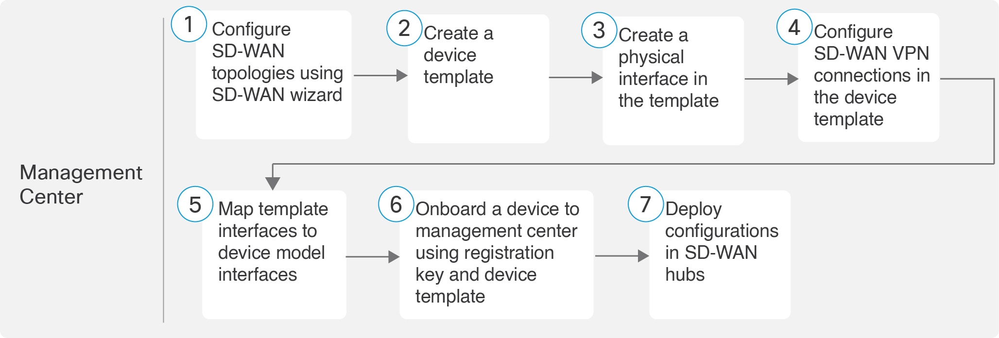
Illustrates the end-to-end workflow to configure a dual ISP SD‑WAN branch office using registration keys and device templates in Firewall Management Center (FMC).

The following flowchart illustrates the workflow for setting up an SD-WAN branch office with dual ISPs using registration key and device templates.

Workflow for setting up an SD-WAN branch office with dual ISPs using registration key and device templates

Step

Task

More Information

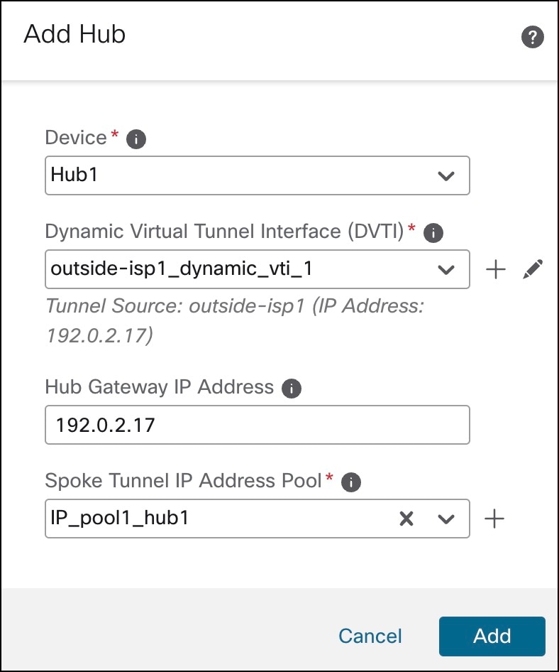
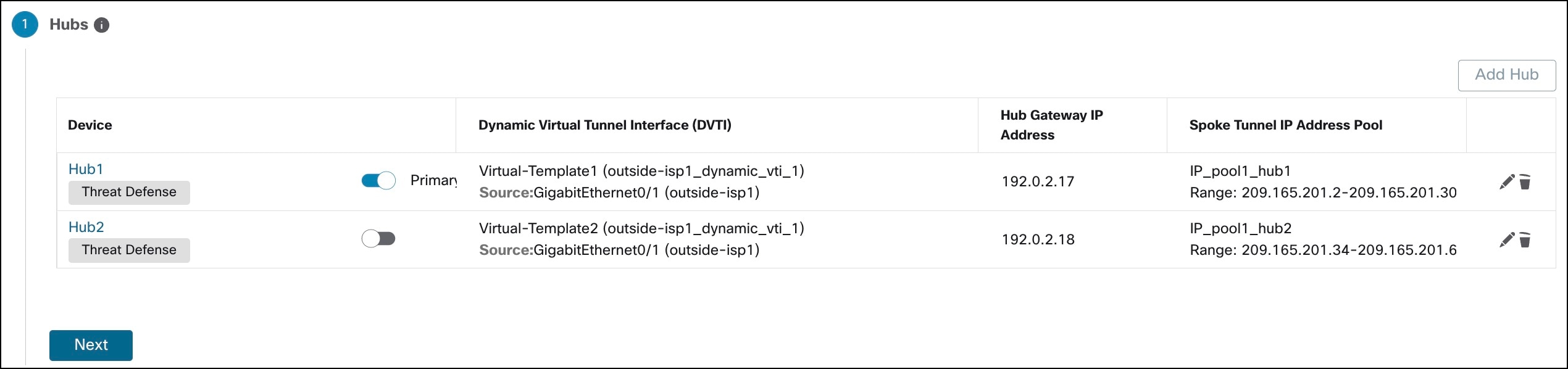
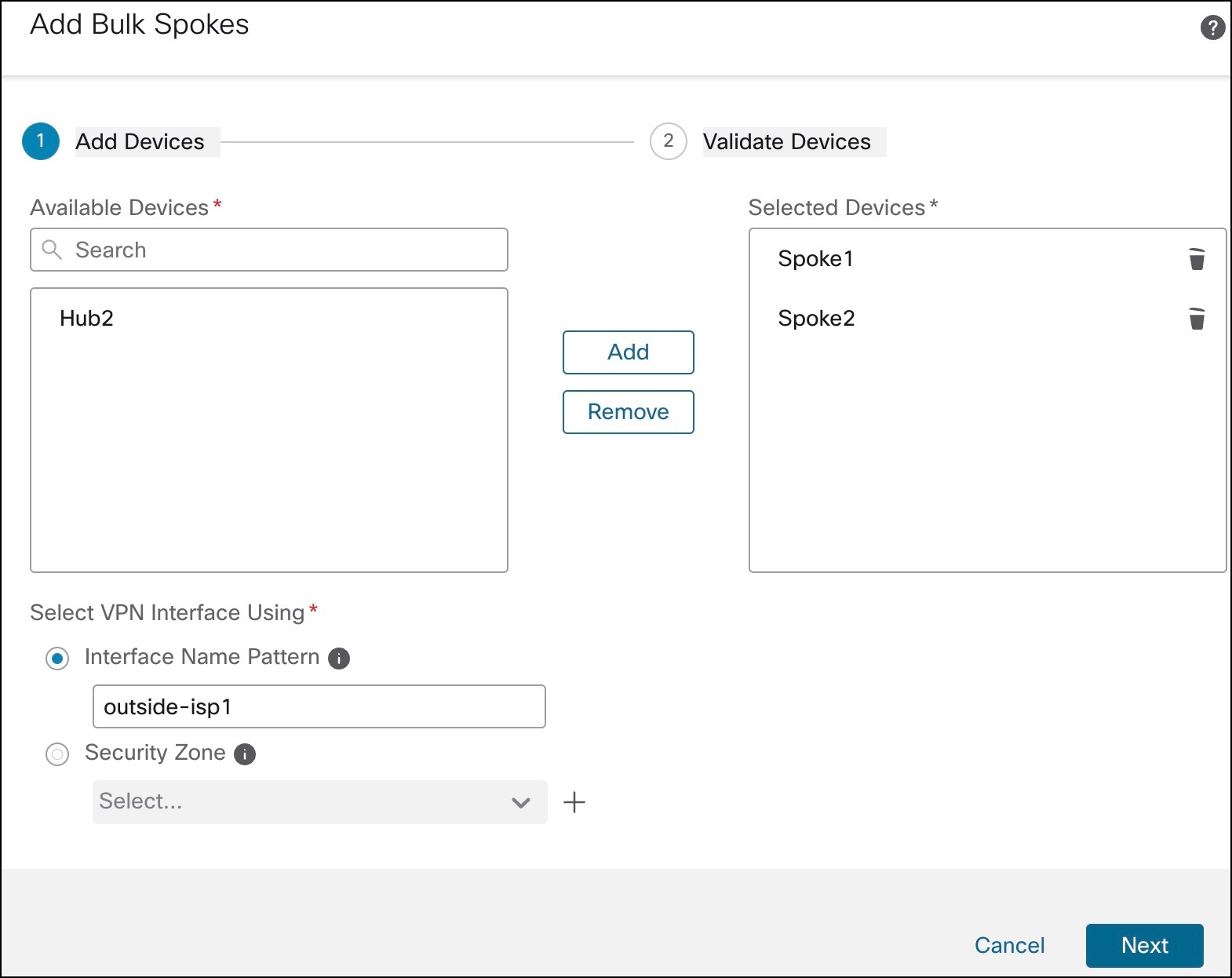
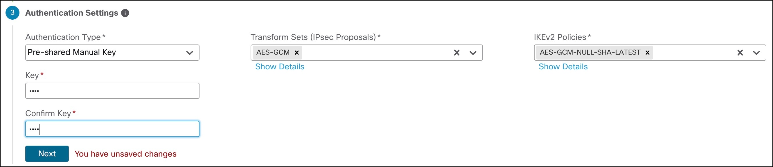
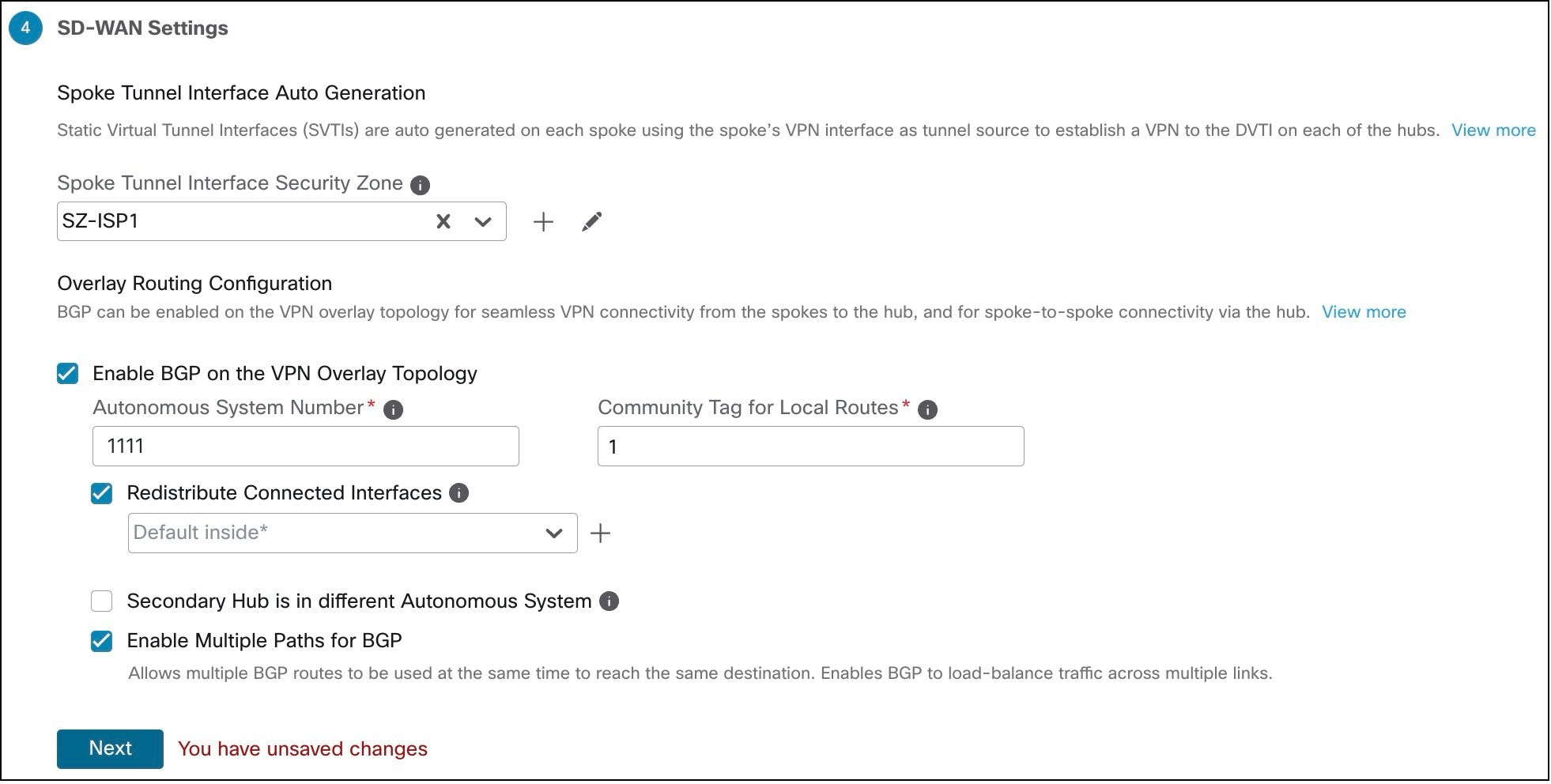
Configure SD-WAN topologies using SD-WAN wizard

Configure SD-WAN Topologies Using the SD-WAN Wizard

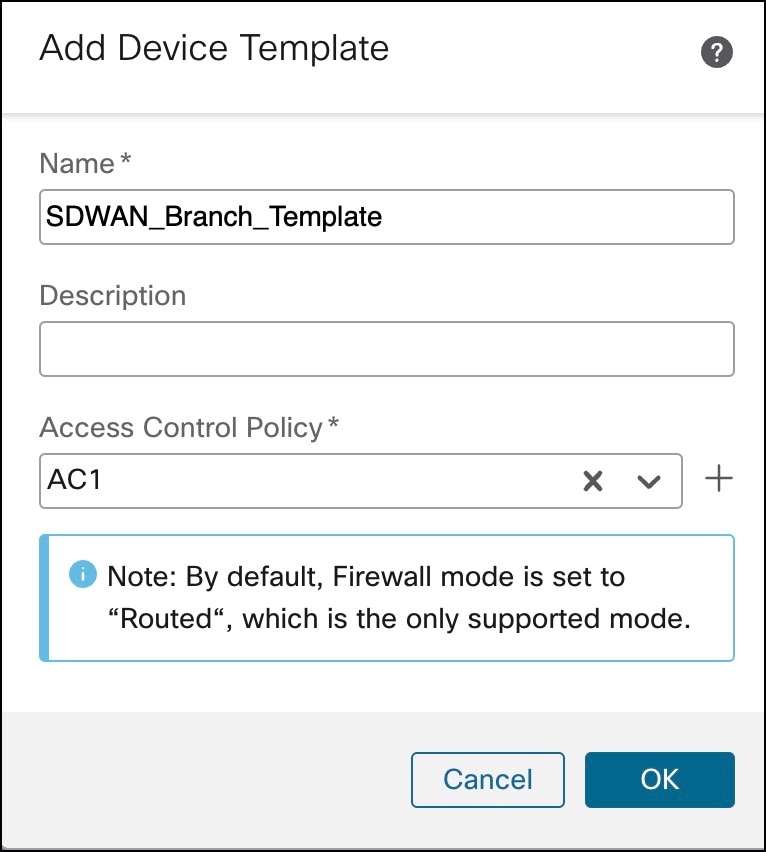
Create a device template

Create a Device Template

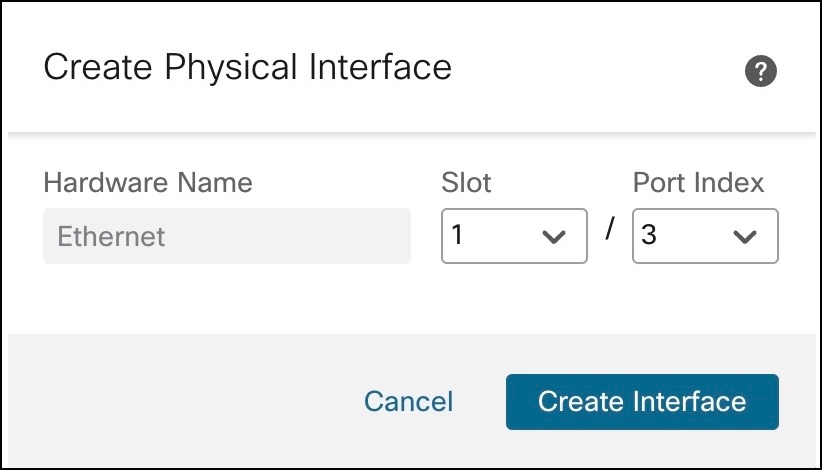
Create a physical interface in the template.

Add a Physical Interface in the Template

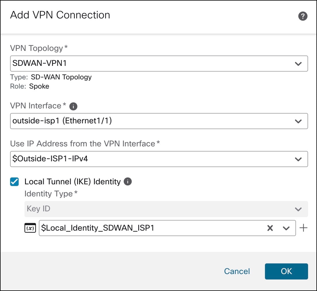
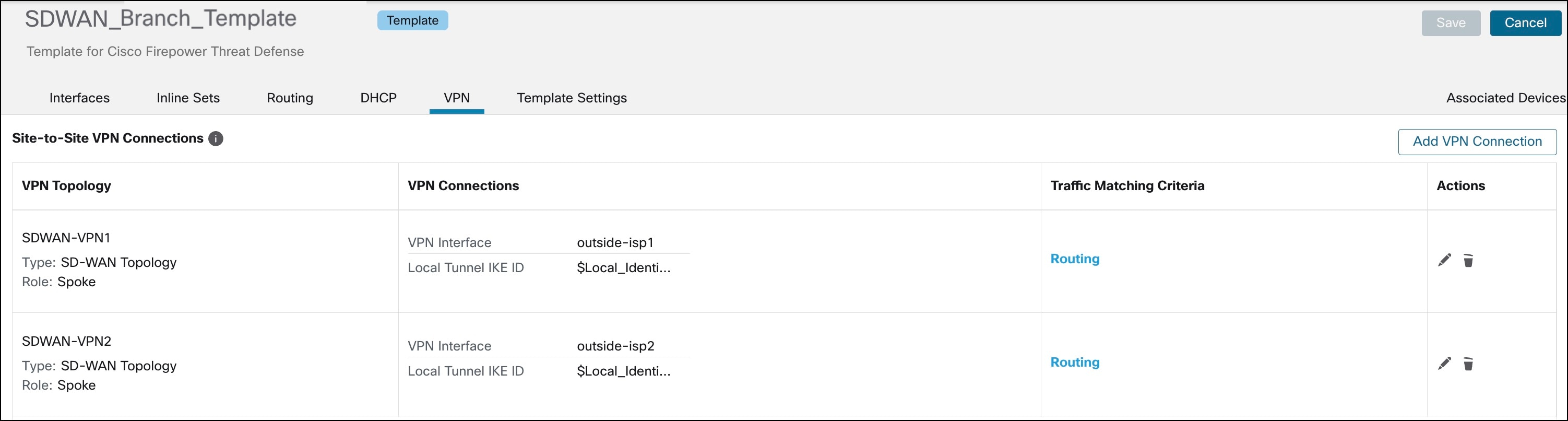
Configure SD-WAN VPN connections in the device template.

Configure an SD-WAN VPN Connection in a Device Template

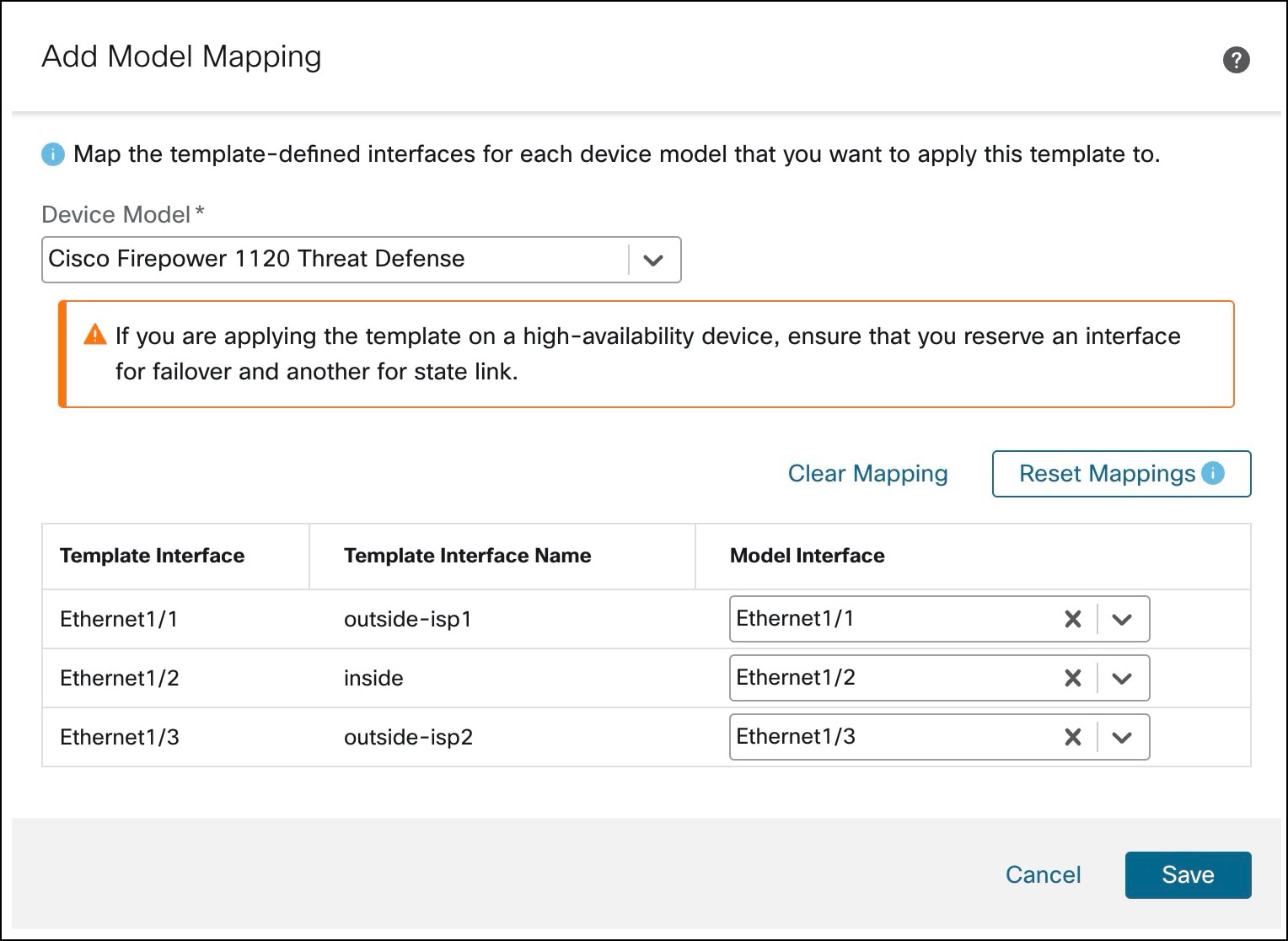
Map template interfaces to device model interfaces.

Map Template Interfaces to Device Model Interfaces

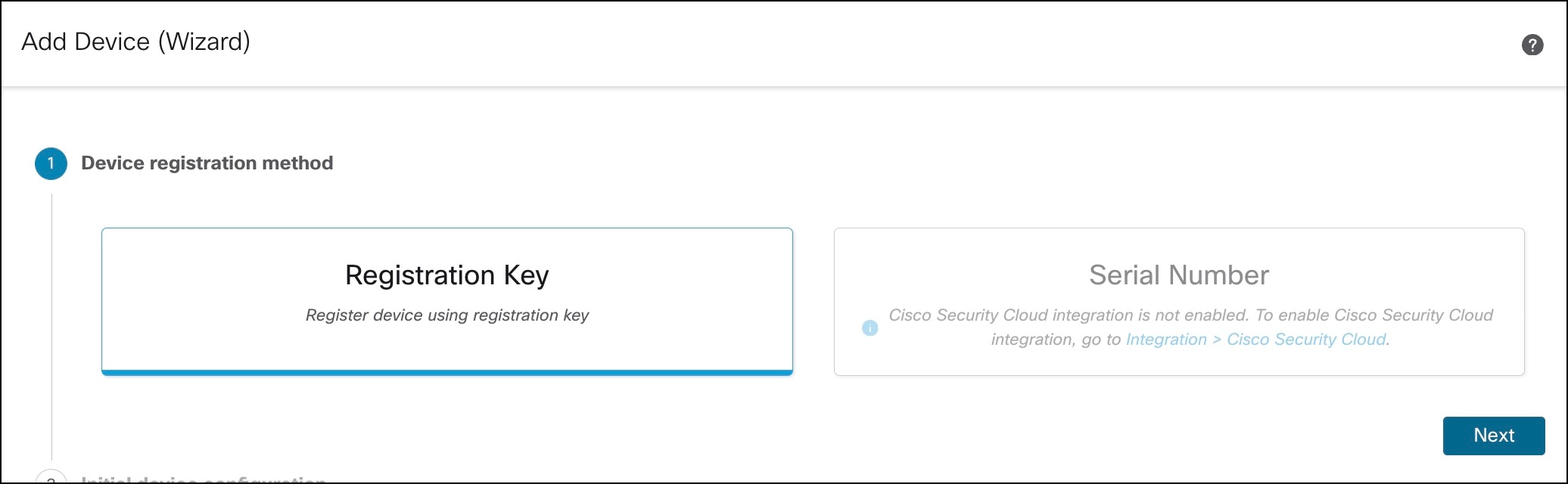
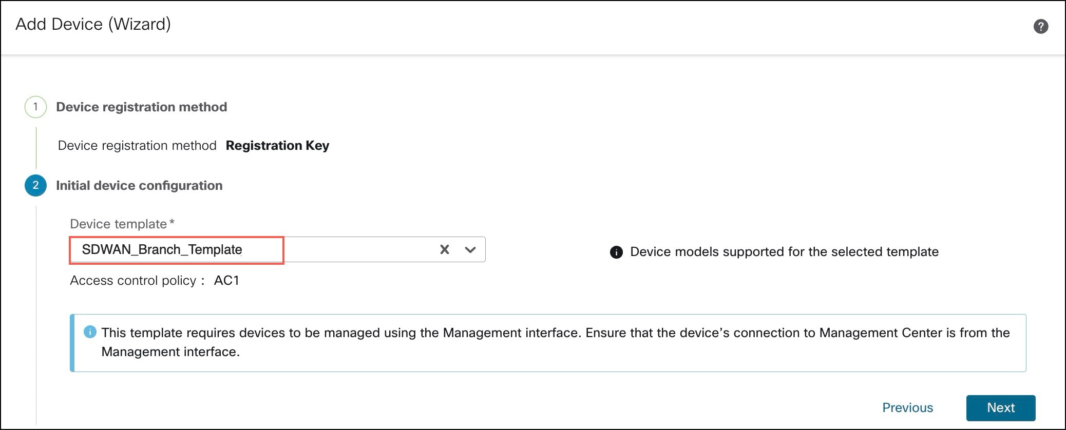
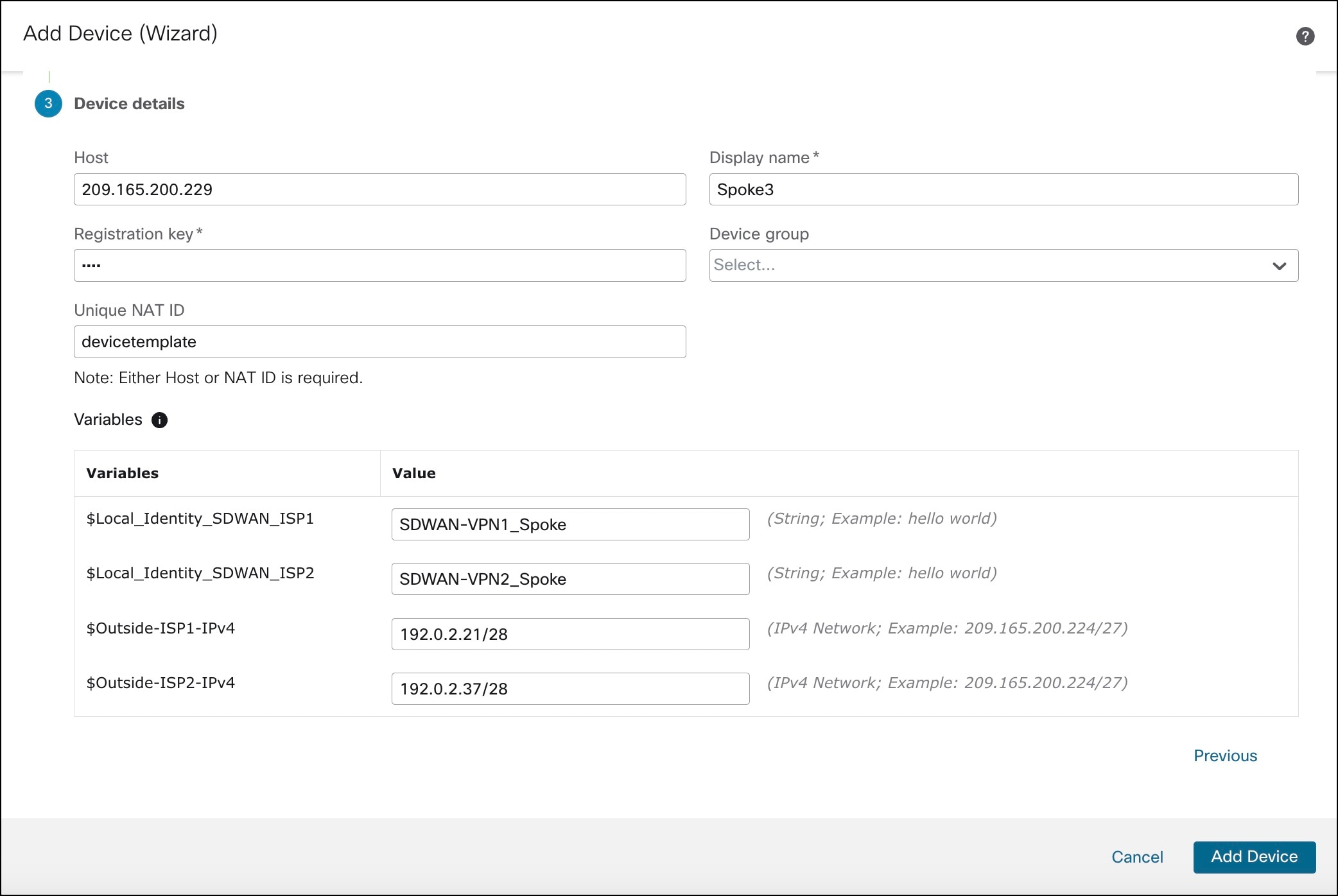
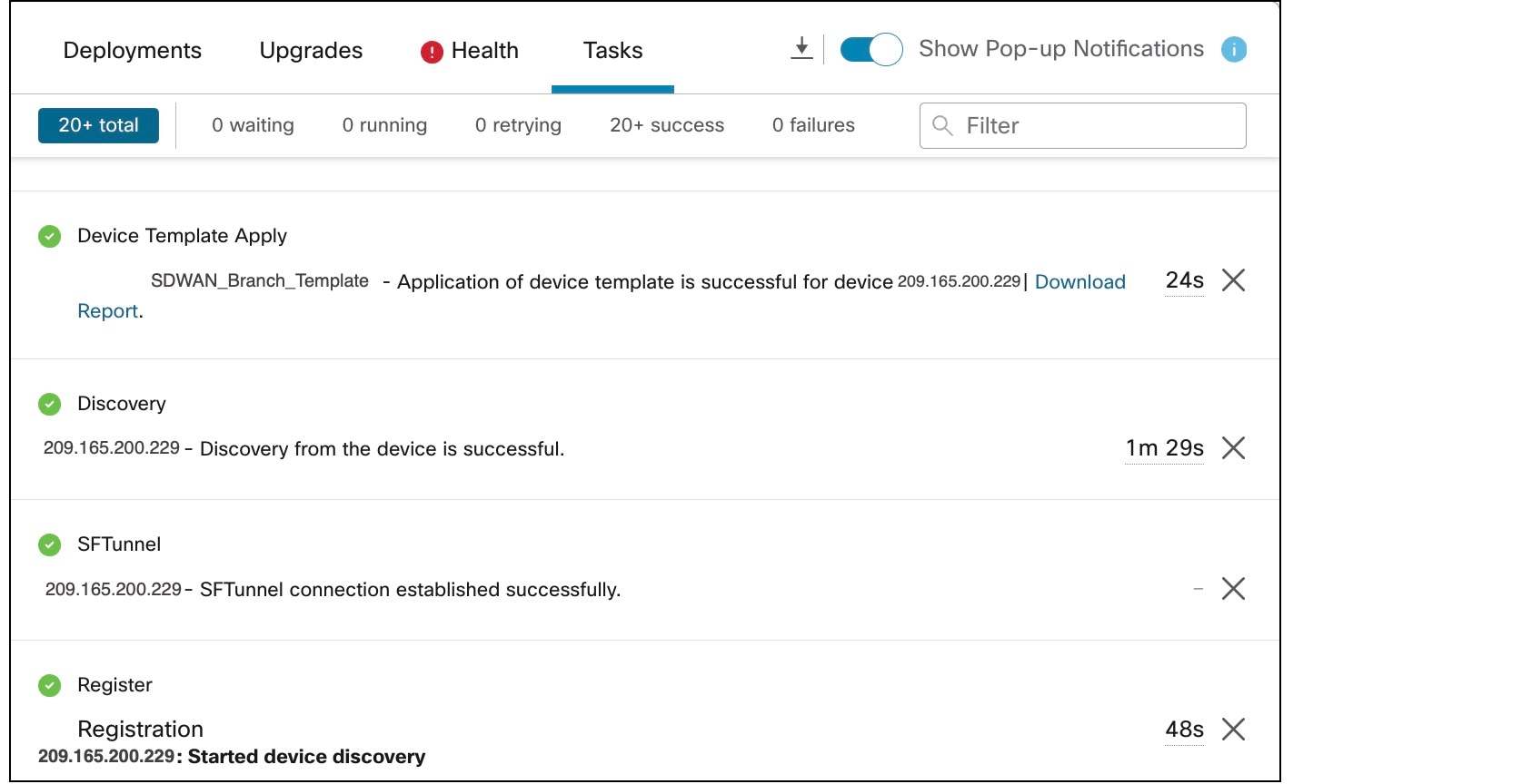
Onboard a device to management center using registration key and device template.

Onboard a Device to Management Center Using a Registration Key and Device Template

Deploy configurations in SD-WAN hubs.

-


Configure SD-WAN Topologies Using the SD-WAN Wizard

The SD-WAN wizard allows you to easily configure VPN tunnels between your centralized headquarters and remote branch sites. Using this wizard, for each spoke, you can use only one WAN interface per SD-WAN topology. However, for dual-ISP setups, you can configure a second SD-WAN topology with the second WAN interface.

In this example, we configure two SD-WAN topologies:

  • SDWAN-VPN1 with outside-isp1 as the spoke's VPN interface for ISP1

  • SDWAN-VPN2 with outside-isp2 as the spoke's VPN interface for ISP2

Procedure

1.

Choose Devices > Site To Site, and click Add.

2.

In the Topology Name field, enter SDWAN-VPN1 as the name for the SD-WAN VPN topology.

3.

Click the SD-WAN Topology radio button and click Create.

4.

Configure a hub:

  1. Click Add Hub.

  2. From the Device drop-down list, choose a hub.

  3. Click + next to the Dynamic Virtual Tunnel Interface (DVTI) drop-down list to add a dynamic VTI for the hub.

    The Add Virtual Tunnel Interface dialog box is prepopulated with default configurations. However, you must configure the following parameters:

    1. From the Tunnel Source drop-down list, choose the physical interface that is the source of the dynamic VTI. Choose the IP address of this interface from the adjacent drop-down list.

    2. From the Borrow IP drop-down list, choose a loopback interface from the drop-down list. The dynamic VTI inherits this IP address.

      • For SDWAN-VPN1: For Hub1, we use Loopback1 (209.165.201.1) as the Borrow IP.

      • For SDWAN-VPN2: For Hub1, we use Loopback2 (209.165.201.65) as the Borrow IP.

      For more information about the loopback IP addresses of the hubs, see Table 2.

  4. Click OK.

  5. In the Hub Gateway IP Address field, enter the public IP address of the hub's VPN interface or the tunnel source of the dynamic VTI to which the spokes connect.

    This IP address is auto populated if the interface has a static IP address. If hub is behind a NAT device, you must manually configure the post-NAT IP address.

    • For SDWAN-VPN1: For Hub1, the Hub Gateway IP Address is 192.0.2.17.

    • For SDWAN-VPN2: For Hub1, the Hub Gateway IP Address is 192.0.2.33.

    For more information about the IP addresses of the hubs and spokes, see Table 1.

  6. From the Spoke Tunnel IP Address Pool drop-down list, choose an IP address pool or click + to create an address pool.

    Note

    Ensure that you do not check the Allow Overrides check box when you create an address pool in the Add IP Pool dialog box.

    When you add spokes, the wizard auto generates spoke tunnel interfaces, and assigns IP addresses to these spoke interfaces from this IP address pool.

  7. Click Add to save the hub configuration.

    Add Hub dialog box in SD-WAN Wizard
  8. (Optional) To add a secondary hub, repeat Step 4a to Step 4g.

    Hubs in SD-WAN Wizard
  9. Click Next.

5.

To configure spokes, click Add Spokes (Bulk Addition). In the Add Bulk Spokes dialog box, configure the following parameters:

  1. Choose Spoke1 and Spoke2 from the Available Devices list and click Add to move the devices to Selected Devices.

  2. Use one of the following methods to select the VPN interfaces of the spokes:

    • Click the Interface Name Pattern radio button and specify a string to match the logical name of the internet or WAN interface of the spokes, for example, outside*, wan*. In our example, the string for the ISP1 interface is outside-isp1.

      If the spoke has multiple interfaces with the same pattern, the first interface that matches the pattern is selected for the topology.

    • Click the Security Zone radio button and choose a security zone with the VPN interfaces of the spokes from the drop-down list, or click + to create a security zone.

    Add Bulk Spokes in SD-WAN Wizard
  3. Click Next.

    The wizard validates if the spokes have interfaces with the specified pattern. Only the validated devices are added to the topology.

  4. Click Add.

  5. Click Next.

For each spoke, the wizard automatically selects the hub's DVTI as the tunnel destination IP address.

Note

If the hub’s tunnel source IP address is an IPv6 address, the wizard automatically selects the first IPv6 address of the spokes' selected interface.​ To edit the IPv6 address of a spoke's tunnel source, click the edit icon next to a spoke, choose an IPv6 address from the IP Address drop-down list, and click Save.

6.

Configure Authentication Settings for the devices in the SD-WAN topology:

  1. From the Authentication Type drop-down list, choose a manual pre-shared key, an auto-generated pre-shared key, or a certificate for device authentication.

    You can use the default settings in this step and proceed to the next step. If required, you can edit the settings later on. In this example, we use Pre-shared Manual Key for device authentication.

    • Pre-shared Manual Key—Specify the pre-shared key for the VPN connection.

    • Pre-shared Automatic Key—(Default value) The wizard automatically defines the pre-shared key for the VPN connection. Specify the key length in the Pre-shared Key Length field. The range is 1 to 127.

    • Certificate—When you use certificates as the authentication method, the peers obtain digital certificates from a CA server in your PKI infrastructure, and use them to authenticate each other.

  2. Choose one or more algorithms from the Transform Sets drop-down list.

  3. Choose one or more algorithms from the IKEv2 Policies drop-down list.

    Authentication Settings in SD-WAN Wizard
  4. Click Next.

7.

Configure the SD-WAN Settings:

This step involves the auto generation of spoke tunnel interfaces, and BGP configuration of the overlay network.

  1. From the Spoke Tunnel Interface Security Zone drop-down list, choose a security zone or click + to create a security zone to which the wizard automatically adds the spokes' auto-generated Static Virtual Tunnel Interfaces (SVTIs).

  2. Check the Enable BGP on the VPN Overlay Topology check box to automate BGP configurations such as neighbor configurations between the overlay tunnel interfaces and basic route redistribution from the directly connected LAN interfaces of the hubs and spokes.

  3. In the Autonomous System Number field, enter an Autonomous System (AS) number.

    AS number is a unique number for a network with a single routing policy. BGP uses AS numbers to identify networks. The spoke's BGP neighbor configuration is generated based on the corresponding hub’s AS number. Range is from 0 to 65536.

    • If all the hubs and spokes are in the same region, by default, 64512 is the AS number.

    • If the primary and secondary hubs are in different regions, the primary hub and the spokes are configured with 64512 as the AS number, and the secondary hub is configured with a different AS number.

  4. In the Community Tag for Local Routes field, enter the BGP community attribute to tag connected and redistributed local routes. This attribute enables easy route filtering. Note this community string, you must use the same community string for the second SD-WAN VPN topology.

  5. Check the Redistribute Connected Interfaces check box and choose an interface group from the drop-down list or click + to create an interface group with connected inside or LAN interfaces for BGP route redistribution in the overlay topology.

  6. Check the Enable Multiple Paths for BGP check box to allow multiple BGP routes to be used at the same time to reach the same destination. This option enables BGP to load-balance traffic across multiple links.

  7. (Optional) Check the Secondary Hub is in Different Autonomous System check box. This check box appears only if you have a secondary hub in this topology.

  8. In the Autonomous System Number field, enter the AS number for the secondary hub. In our example, both the hubs are in the same region and have the same AS number.

  9. In the Community Tag for Learned Routes field, enter the BGP community attribute to tag routes learned from other SD-WAN peers over the VPN tunnel. This attribute is required only for eBGP configuration when the secondary hub has a different AS number. This field appears only if you have configured two hubs in the SD-WAN topology. In our example, we do not have to configure this value because all the devices are in the same region.

    SD-WAN Settings in SD-WAN Wizard
  10. Click Next.

8.

Click Finish to save and validate the SD-WAN topology.

You can view the topology in the Site-to-Site VPN Summary page (Devices > Site-to-site VPN). After you deploy the configurations to all the devices, you can see the status of all the tunnels in this page.

What to do next

  1. Repeat Step 1 to Step 8 to configure the SDWAN-VPN2 topology with the VPN interface for ISP2: outside-isp2.

  2. Configure a point-to-point route-based VPN topology between the two hubs using the route-based VPN wizard to ensure direct communication between these networks.


Create a Device Template

Before you begin

You must be an admin user to create a device template.

Procedure

1.

Choose Devices > Template Management.

2.

Click Add Device Template.

In the Add Device Template dialog box, configure the following parameters:

  1. In the Name field, enter the name for the template.

  2. (Optional) In the Description field, enter a description for the template.

  3. From the Access Control Policy drop-down list, choose an access control policy.

Add Device Template dialog box
3.

Click OK.


Add a Physical Interface in the Template

By default, a device template enables the device to come up with the following physical interfaces:

  • Management interface

  • Inside interface

  • Outside interface

For this dual ISP use case, we need two outside interfaces. To create a physical interface:

Procedure

1.

Choose Devices > Template Management.

2.

Click the edit icon of the template in which you want to add the physical interface.

3.

In the Interfaces tab, click Add Physical Interface.

4.

Choose a Slot and Port Index number from the drop-down list.

5.

Click Create Interface.

Create physical interface in a device template

You can rename the outside interfaces of the device template. In this example, these interfaces are outside-isp1 and outside-isp2.


Configure an SD-WAN VPN Connection in a Device Template

You must configure an SD-WAN VPN connection to add spokes to SD-WAN topologies using the device template.

Before you begin

Procedure

1.

Choose Devices > Template Management.

2.

Click the edit icon adjacent to the device template that you want to edit.

3.

Click the VPN tab.

4.

Click Add VPN Connection.

5.

Choose an SD-WAN topology from the VPN Topology drop-down list.

The Add VPN Connection dialog box expands and you can configure the following parameters:

  1. From the VPN Interface drop-down list, choose a WAN-facing or internet-facing physical interface to establish a VPN connection with the hub.

    This list contains all the interfaces configured in the device template. In this example, the VPN interface is outside-isp1.

  2. Use IP Address from the VPN Interface—This drop-down list is auto populated with the IP address variable. For IPv6 address, choose an IPv6 address from the drop-down list.

  3. Check the Local Tunnel (IKE) Identity check box to enable a unique and configurable identity for the VPN tunnel from the spoke to a remote peer.

  4. Identity Type—Key ID is the only supported identity type. Choose a key ID variable from the drop-down list or click + to create a new key ID variable.

  5. Click OK.

    Add VPN Connection in Device Templates

    You can view the VPN connection in the Site-to-Site VPN Connections table.

6.

Click Save.

7.

Repeat Step 4 to Step 6 to configure another SD-WAN VPN connection using the second outside interface.

In this example, the second outside interface is outside-isp2, and there are two SD-WAN VPN connections:

  • SDWAN-VPN1 with outside-isp1 as the VPN interface

  • SDWAN-VPN2 with outside-isp2 as the VPN interface

Site-to-Site VPN Connections in Device Templates

Map Template Interfaces to Device Model Interfaces

For each model, you can specify which template interface corresponds to which model interface. You can map a template to one or more models as long as the interface configurations are valid for all the mapped models. For example, if the template includes switch ports and VLAN interfaces, then that template can only be applied to a Firepower 1010.

Procedure

1.

Choose Devices > Template Management.

2.

Click Add Model Mapping for the template in which you want to create the model mapping. Alternatively, you can click the edit icon of the template and choose Template Settings > Model Mapping.

3.

Click Add Model Mapping

4.

Choose the Device Model from the drop-down list.

In this example, we choose a Cisco Firepower 1120 Threat Defense device.

5.

Map the template interfaces to the device model interfaces by choosing the interface from the Model Interface drop-down list.

Note

Click Clear Mapping to remove defined model mapping. Click Reset Mappings for default interface mapping in which the mapping is done based on the slot and port index order of the interface names.

6.

Click Save.

Note

Some configurations in the template may not be supported on all device models. Unsupported configurations, if any, are not applied to the device. The Device Template Apply Report provides details about such configurations.

Add Model Mapping in Device Template

Onboard a Device to Management Center Using a Registration Key and Device Template

You can use the device template to add a device, register the device with Management Center, and bring up the device with the given template configurations.

We recommend that you create a checklist to ensure that all the configurations in the template have been entered correctly before applying the template on the device.

The following is a sample checklist:

  • Check version, model, operation modes.

  • Check list of variables and overrides.

  • Check sanity of variable and override values.

  • Check if the required model mappings exist.

  • Check if parallel device template operations are in progress.

Note

If you add a Threat Defense device that will be managed by a data interface for Management Center connectivity, ensure that you configure the template to be compatible with the connectivity parameters of the device. For more information, see Configure a Template for Threat Defense Devices Managed Through the Data Interface.

Procedure

1.

Choose Devices > Device Management.

2.

Click Add > Device (Wizard).

3.

In the Add Device (Wizard) window, choose Registration Key to register a device using registration key.

Step 1 of Add Device Wizard
4.

Click Next.

5.

Choose a template from the Device template drop-down list.

Step 2 of Add Device Wizard
6.

Click Next.

7.

In the Host field, enter the IP address or the hostname of the device you want to add.

The hostname of the device is the fully qualified domain name or the name that resolves through the local DNS to a valid IP address. Use a hostname rather than an IP address if your network uses DHCP to assign IP addresses.

8.

In the Display name field, enter a name for the device as you want it to display in the management center.

9.

In the Registration key field, enter the same registration key that you used when you configured the device to be managed by the management center. The registration key is a one-time-use shared secret. The key can include alphanumeric characters and hyphens (-).

10.

(Optional) From the Device group drop-down list, choose a device group in which the device is added.

11.

Enter values for the Variables and Network object overrides.

Step 3 of Add Device Wizard
12.

Click Add Device to initiate device registration.

The template configurations are applied after the device is successfully registered with the Management Center.

In the Notifications > Tasks window, you can view the messages related to the device registration, device discovery, and device template application.

Notifications about device registration and template application on a device

A Device Template Apply report is generated after the apply template task is completed. This report is generated on both successful and unsuccessful application of the template on the device. You will see a link to this report in the Notifications > Tasks window.