Overview
Provides instructions for creating a route-based site-to-site VPN between a hub and a branch site using Firewall Management Center (FMC).
You can configure a route-based site-to-site VPN between two nodes. To configure a VTI-based VPN you need virtual tunnel interfaces at both the nodes of the tunnel.
For managed spokes, you can configure a backup static VTI interface along with the primary VTI interface.
Procedure
| 1. | Choose Devices > VPN > Site To Site. |
|
| 2. | Enter the name as Corporate-VPN in the Topology Name field. |
|
| 3. | Choose Route Based (VTI) as the topology type. |
|
| 4. | Configure the endpoint for the hub node. See Configure the Endpoint for the Hub Node. |
|
| 5. | Configure the endpoint for the spoke node. See Configure the Endpoint for the Spoke Node. |
|
| 6. | The default settings are used in the IKE, IPsec, and Advanced tabs. |
|
| 7. | Click Save. The Corporate-VPN topology is created successfully. |
|
| 8. | You can view the VPN topology in the Site-to-site VPN listing page by navigating to Devices > Site-to-site VPN.
|
|
| 9. | Expand the Corporate-VPN node to view all the tunnels in the topology. It displays the NGFW1 hub and the NGFWBR1 spoke with details of the physical source and VTI interfaces. Since the configuration has not yet been deployed, it displays Deployment Pending and the tunnel displays amber status. 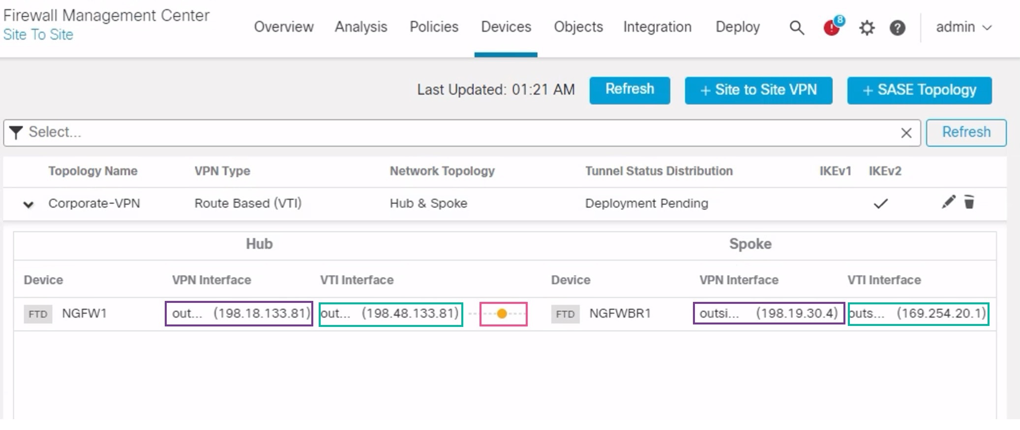
|
What to do next
After you configure VTI interfaces and VTI tunnel on both the devices, you must configure:
-
A routing protocol to route the VTI traffic between the devices over the VTI tunnel. See Configure OSPF on the Hub Node and Configure OSPF on the Spoke Node.
-
An access control rule to allow encrypted traffic. See Configure the Access Control Policy.