Overview
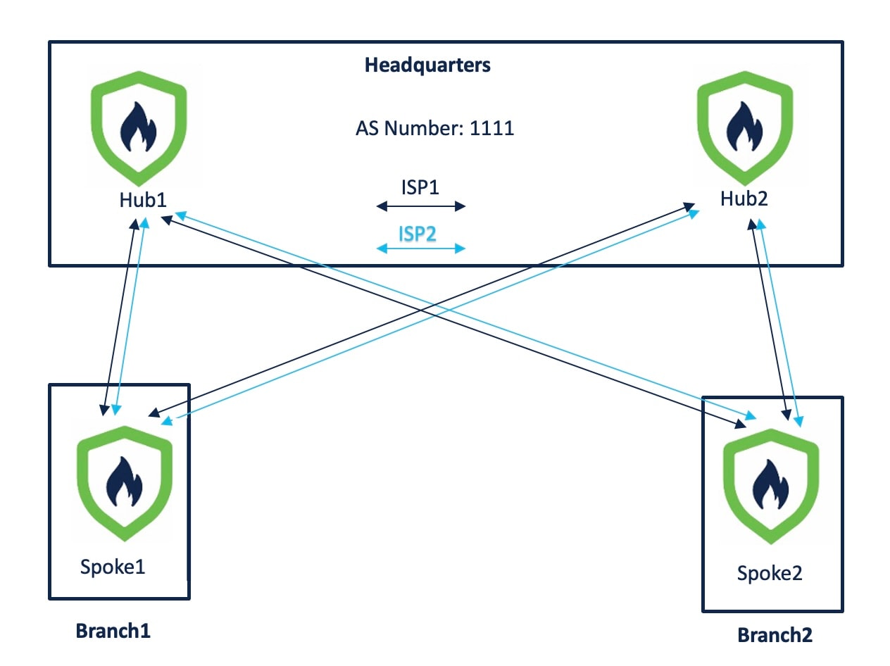
Illustrates a sample dual ISP network topology with branch devices connecting over dual ISP links and integrating with Firewall Management Center (FMC).
In the following sample dual ISP topology, the hubs and spokes are in a single region, with autonomous system (AS) number as 1111. The hubs and spokes use Internal Border Gateway Protocol (iBGP) as the routing protocol to exchange routing information.
-
Hub1 and Hub2 are Firewall Threat Defense hub devices at the headquarters.
-
Spoke1 and Spoke2 are Firewall Threat Defense spoke devices at the branches.
-
outside-isp1 is the VPN interface of each spoke to ISP1.
-
outside-isp2 is the VPN interface of each spoke to ISP2.
Alex aims to onboard a Cisco Firepower 1120 Firewall Threat Defense device into an existing dual ISP SD-WAN topology with preconfigured device settings. Utilizing the new intuitive SD-WAN VPN wizard and device templates, he can efficiently create SD-WAN VPN topologies and streamline the onboarding process for the device in the SD-WAN topology.
The topology has the following parameters:
| Device | Management IP Address | Inside Interface | Outside Interface |
|---|---|---|---|
| Hub1 | 209.165.200.225 | 198.51.100.17/28 |
|
| Hub2 | 209.165.200.226 | 198.51.100.33/28 |
|
| Spoke1 | 209.165.200.227 | 198.51.100.65/28 |
|
| Spoke2 | 209.165.200.228 | 198.51.100.129/28 |
|
| Device | Hub Loopback IP Addresses | IP Address Pools |
|---|---|---|
| Hub1 |
|
|
| Hub2 |
|
|
When you configure the hub IP address pools, ensure that you do not check the Allow Overrides check box in the Add IPv4/IPv6 Pool dialog box (Objects > Object Management > Address Pools). You can also create these address pools in the SD-WAN wizard.