Use Cases for SD-WAN Capabilities in Cisco Secure Firewall

PDF

Configure the Endpoint for the Spoke Node

Updated: February 5, 2026

Overview

Provides instructions for configuring a Threat Defense (FTD) device as a branch site spoke in a route-based site-to-site VPN using Firewall Management Center (FMC).

Procedure

1.

In the Spoke Nodes section, click +. The Add Endpoint dialog box is displayed.

2.

Choose NGFWBR1 as the hub from the Device drop-down list.

Note

The device must be running on software version 7.3 or later.

3.

Click + next to the Static Virtual Tunnel Interface drop-down list to add a new static VTI.

The Add Virtual Tunnel Interface dialog box appears with the following pre-populated default configurations.

  • Tunnel Type is auto-populated with Static.

  • Name is auto-populated as <tunnel_source interface logical name>+ static_vti +<tunnel ID>. For example, outside_static_vti_1 .

  • The Enabled checkbox is checked by default.

  • Select Tunnel_Zone from the Security Zone drop-down list.

  • Tunnel ID is auto-populated with a value as 1.

  • Select GigabitEthernet0/4 (outside3) from the Tunnel Source drop-down list. Select the IP address of the outside 3 interface as 198.19.30.4 from the drop-down list next to it.

  • IPsec Tunnel Mode is set to IPv4, by default.

  • IP address can either be a static IP address or a borrow IP. We recommend that you configure the Borrow IP for the static interface from a loopback interface. To add a loopback interface, click + next to the Borrow IP (IP unnumbered) drop-down list. In the Add Loopback Interface dialog box:

    1. In the General tab, enter the Name as Spoke_Tunnel_IP and Loopback ID as 1.

    2. In the IPv4 tab, enter the IP address as 169.254.20.1/32 .

    3. Click OK to save the loopback interface.

    The Borrow IP is set to Loopback 1(Spoke_Tunnel_IP).

Click OK to save the SVTI. A message is displayed that confirms the VTI is created successfully. Click OK.

The Static Virtual Tunnel Interface is set to outside_static_vti_1(169.254.20.1).

4.

Expand Advanced Settings to view the default settings. Both checkboxes must be checked.

5.

Click OK.

NGFWBR1 is successfully configured as the spoke node.
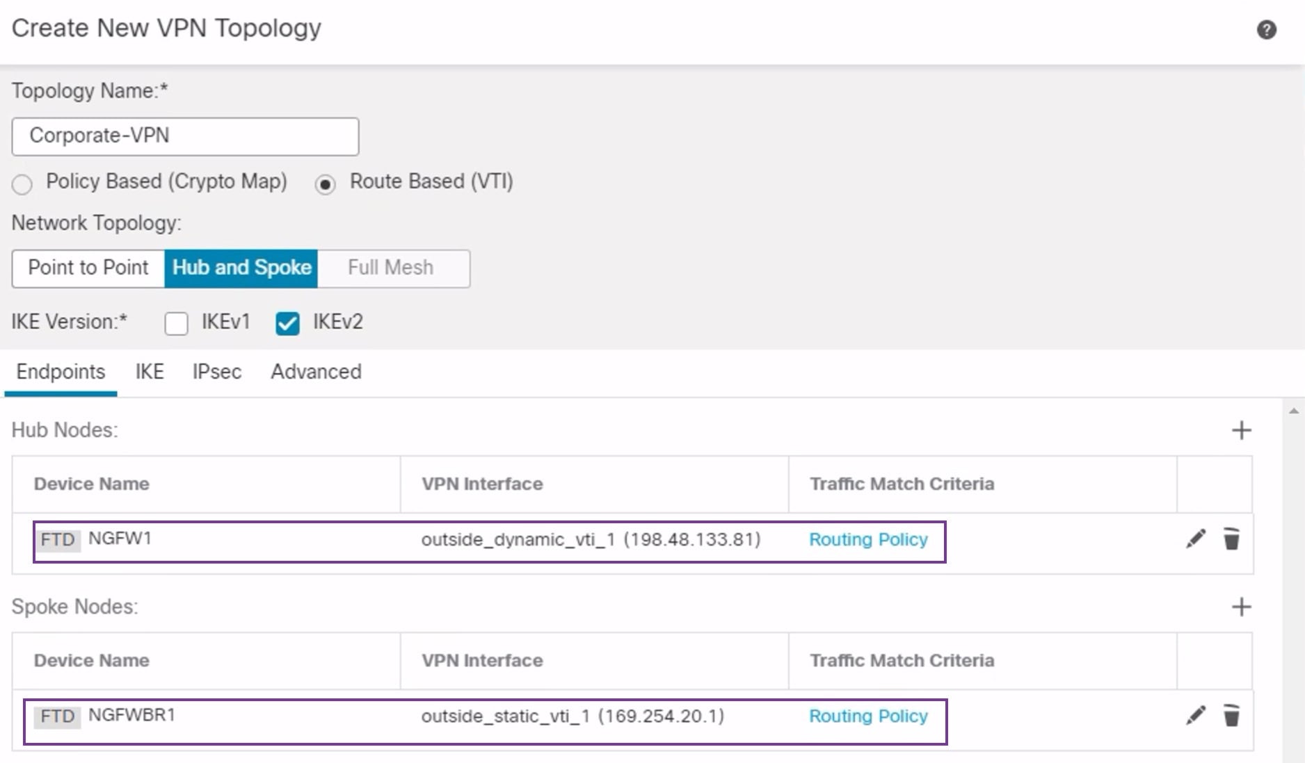
Screenshot of hub and spoke devices in the VPN wizard in Firewall Management Center