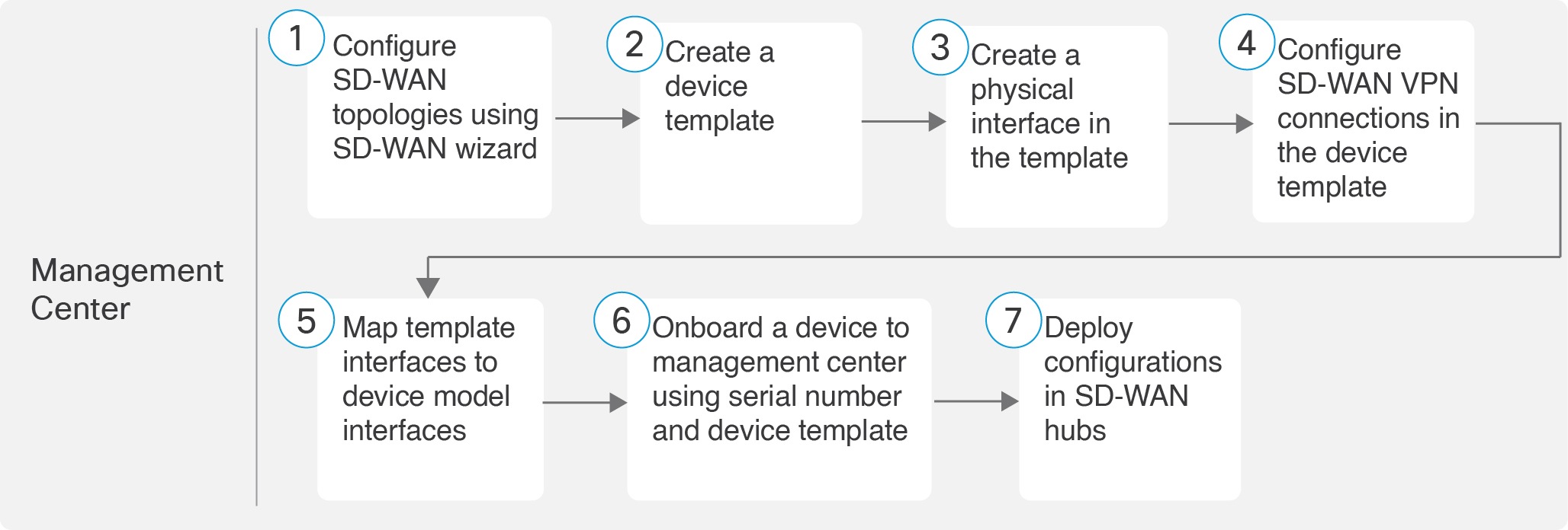
Illustrates the end-to-end workflow to configure a dual ISP SD‑WAN branch office using device serial numbers and templates in Firewall Management Center (FMC).
The following flowchart illustrates the workflow for setting up an SD-WAN branch office with dual ISPs using serial number and device templates.
Configure SD-WAN Topologies Using the SD-WAN Wizard
The SD-WAN wizard allows you to easily configure VPN tunnels between your centralized headquarters and remote branch sites. Using this wizard, for each spoke, you can use only one WAN interface per SD-WAN topology. However, for dual-ISP setups, you can configure a second SD-WAN topology with the second WAN interface.
This example describes how to configure two SD-WAN topologies:
SDWAN-VPN1 with outside-isp1 as the spoke's VPN interface for ISP1
SDWAN-VPN2 with outside-isp2 as the spoke's VPN interface for ISP2
In the Topology Name field, enter SDWAN-VPN1 as the name for the SD-WAN VPN topology.
3.
Click the SD-WAN Topology radio button and click Create.
4.
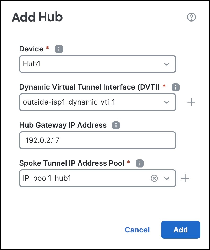
Configure a hub:
Click Add Hub.
From the Device drop-down list, choose a hub.
Click + next to the Dynamic Virtual Tunnel Interface (DVTI) drop-down list to add a dynamic VTI for the hub.
The Add Virtual Tunnel Interface dialog box is prepopulated with default configurations. However, you must configure the following parameters:
From the Tunnel Source drop-down list, choose the physical interface that is the source of the dynamic VTI. Choose the IP address of this interface from the adjacent drop-down list.
From the Borrow IP drop-down list, choose a loopback interface. The dynamic VTI inherits this IP address.
For SDWAN-VPN1: For Hub1, we use Loopback1 (209.165.201.1) as the Borrow IP address.
For SDWAN-VPN2: For Hub1, we use Loopback2 (209.165.201.65) as the Borrow IP address.
For more information about the loopback IP addresses of the hubs, see Table 2.
Click OK.
In the Hub Gateway IP Address field, enter the public IP address of the hub's VPN interface or the tunnel source of the dynamic VTI to which the spokes connect.
This IP address is auto populated if the interface has a static IP address. If hub is behind a NAT device, you must manually configure the post-NAT IP address.
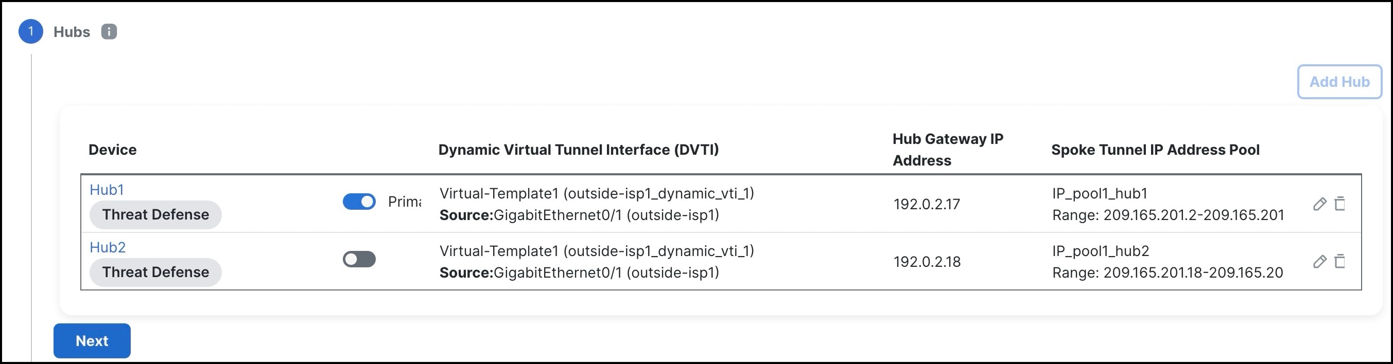
For SDWAN-VPN1: For Hub1, the Hub Gateway IP Address is 192.0.2.17.
For SDWAN-VPN2: For Hub1, the Hub Gateway IP Address is 192.0.2.33.
For more information about the IP addresses of the hubs and spokes, see Table 1.
From the Spoke Tunnel IP Address Pool drop-down list, choose an IP address pool or click + to create an address pool.
When you add spokes, the wizard auto generates spoke tunnel interfaces, and assigns IP addresses to these spoke interfaces from this IP address pool.
Note
Ensure that you do not check the Allow Overrides check box when you create an address pool in the Add IP Pool dialog box.
Click Add to save the hub configuration.
To add the secondary hub, repeat Step 4a to Step 4g.
Click Next.
5.
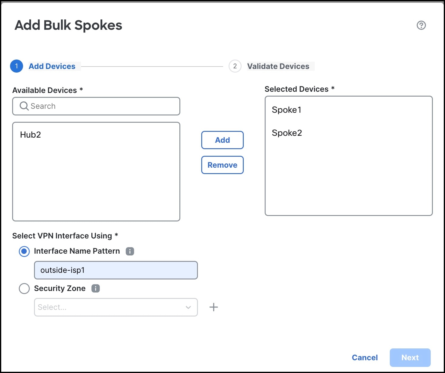
To configure spokes, click Add Spokes (Bulk Addition).
In the Add Bulk Spokes dialog box, configure the following parameters:
Choose Spoke1 and Spoke2 from the Available Devices list and click Add to move the devices to Selected Devices.
Use one of the following methods to select the VPN interfaces of the spokes:
Click the Interface Name Pattern radio button and specify a string to match the logical name of the internet or WAN interface of the spokes, for example, outside*, wan*. In our example, the string for the ISP1 interface is outside-isp1.
Note
If the spoke has multiple interfaces with the same pattern, the first interface that matches the pattern is selected for the topology.
Click the Security Zone radio button and choose a security zone with the VPN interfaces of the spokes from the drop-down list, or click + to create a security zone.
Click Next.
The wizard validates if the spokes have interfaces with the specified pattern. Only the validated devices are added to the topology.
Click Add.
Click Next.
For each spoke, the wizard automatically selects the hub's DVTI as the tunnel destination IP address.
Note
If the hub’s tunnel source IP address is an IPv6 address, the wizard automatically selects the first IPv6 address of the spokes' selected interface. To edit the IPv6 address of a spoke's tunnel source, click the edit icon next to a spoke, choose an IPv6 address from the IP Address drop-down list, and click Save.
6.
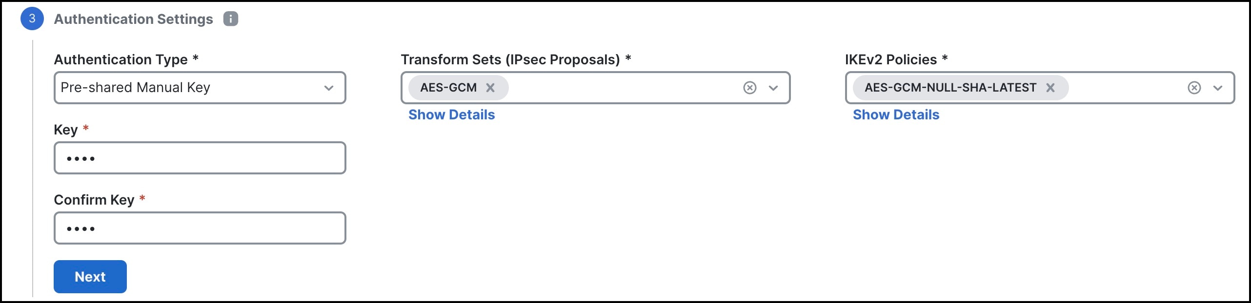
Configure Authentication Settings for the devices in the SD-WAN topology:
You can use the default settings and proceed to Step 7. If required, you can edit the settings later. In this example, we use pre-shared manual key for device authentication.
From the Authentication Type drop-down list, choose a manual pre-shared key, an auto-generated pre-shared key, or a certificate for device authentication.
Pre-shared Manual Key—Specify the pre-shared key for the VPN connection.
Pre-shared Automatic Key—(Default value) The wizard automatically defines the pre-shared key for the VPN connection. Specify the key length in the Pre-shared Key Length field. The range is 1 to 127.
Certificate—When you use certificates as the authentication method, the peers obtain digital certificates from a CA server in your PKI infrastructure, and use them to authenticate each other.
Choose one or more algorithms from the Transform Sets drop-down list.
Choose one or more algorithms from the IKEv2 Policies drop-down list.
Click Next.
7.
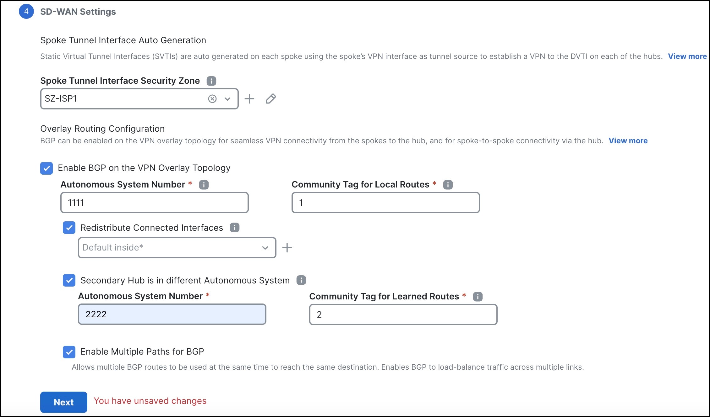
Configure the SD-WAN Settings.
This step involves the auto generation of spoke tunnel interfaces, and BGP configuration of the overlay network.
From the Spoke Tunnel Interface Security Zone drop-down list, choose a security zone or click + to create a security zone to which the wizard automatically adds the spokes' auto-generated Static Virtual Tunnel Interfaces (SVTIs).
Check the Enable BGP on the VPN Overlay Topology check box to automate BGP configurations such as neighbor configurations between the overlay tunnel interfaces and basic route redistribution from the directly connected LAN interfaces of the hubs and spokes.
In the Autonomous System Number field, enter an Autonomous System (AS) number.
AS number is a unique number for a network with a single routing policy. BGP uses AS numbers to identify networks. The spoke's BGP neighbor configuration is generated based on the corresponding hub’s AS number. Range is from 0 to 65536.
If all the hubs and spokes are in the same region, by default, 64512 is the AS number.
If the primary and secondary hubs are in different regions, the primary hub and its spokes are configured with 64512 as the AS number, and the secondary hub is configured with a different AS number.
In our example, Hub1 and the spokes are in the same region with AS number as 1111. Hub2 is in a different region with AS number as 2222.
In the Community Tag for Local Routes field, enter the BGP community attribute to tag the connected and redistributed local routes. This attribute enables easy route filtering. Make a note of this community string; you must use the same community string for the second SD-WAN VPN topology. In our example, this tag is 1.
Check the Redistribute Connected Interfaces check box and choose an interface group from the drop-down list, or click + to create an interface group with connected inside or LAN interfaces for BGP route redistribution in the overlay topology.
Check the Secondary Hub is in different Autonomous System check box. This check box is displayed only if you have a secondary hub in this topology.
In the Autonomous System Number field, enter the AS number for the secondary hub. In our example, Hub2 is in a different region with AS number as 2222.
In the Community Tag for Learned Routes field, enter the BGP community attribute to tag the routes learned from other SD-WAN peers over the VPN tunnel. This attribute is required only for eBGP configuration when the secondary hub has a different AS number. This field appears only if you have configured two hubs in the SD-WAN topology. Make a note of this community string, you must use the same community string for the second SD-WAN VPN topology. In our example, this tag is 2.
Check the Enable Multiple Paths for BGP check box to allow multiple BGP routes to be used at the same time to reach the same destination. This option enables BGP to load-balance traffic across multiple links.
Click Next.
8.
Click Finish to save and validate the SD-WAN topology.
You can view the topology in the Site-to-Site VPN Summary page (Devices > Site-to-site VPN). After you deploy the configurations to all the devices, you can see the status of all the tunnels in this page.
9.
Repeat Step 1 to Step 8 to configure the SDWAN-VPN2 topology with the VPN interface for ISP2: outside-isp2.
What to do next
Configure a point-to-point route-based VPN topology between the two hubs using the route-based VPN wizard to ensure direct communication between these networks. For more information, see Configure a Policy-based Site-to-Site VPN.
Map Template Interfaces to Device Model Interfaces
For each model, you can specify which template interface corresponds to which model interface. You can map a template to one or more models as long as the interface configurations are valid for all the mapped models. For example, if the template includes switch ports and VLAN interfaces, then that template can only be applied to a Firepower 1010.
Procedure
1.
Choose Devices > Template Management.
2.
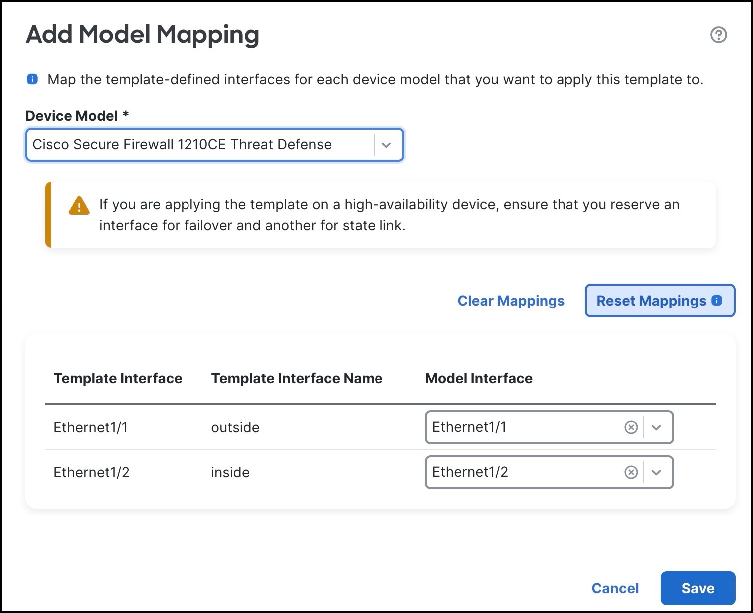
Click Add Model Mapping for the template in which you want to create the model mapping. Alternatively, you can click the edit icon of the template and choose Template Settings > Model Mapping.
3.
Choose the Device Model from the drop-down list.
In this example, we choose a Cisco Firepower 1010 Threat Defense device.
4.
Map the template interfaces to the device model interfaces by choosing the interface from the Model Interface drop-down list.
Note
Click Clear Mapping to remove the defined model mapping. Click Reset Mappings for default interface mapping in which the mapping is done based on the slot and port index order of the interface names.
5.
Click Save.
Note
Some configurations in the template may not be supported on all device models. Unsupported configurations, if any, are not applied to the device. The Device Template Apply Report provides details about such configurations.
Onboard a Device to Management Center Using a Serial Number and Device Template
Zero-Touch Provisioning lets you register devices to the using serial number without any initial setup on the device. You can use a template to add a device, register the device with the and bring up the device with template configurations. You can register up to 25 devices at a time. For serial number registration, define all variables and overrides in a CSV file that you upload.
Before you begin
Before you add a device using a serial number, you must integrate the with Cisco Security Cloud.
Security Cloud Control onboards the on-prem after you integrate it with Cisco Security Cloud. Security Cloud Control needs the in its inventory for zero-touch provisioning to operate. However, you do not need to use Security Cloud Control directly. If you do use Security Cloud Control, its support is limited to device onboarding, viewing its managed devices, viewing objects associated with the , and cross-launching the .
Choose Integration > Cisco Security Cloud.
Click Enable Cisco Security Cloud to open a separate browser tab to log you into your Cisco Security Cloud account and confirm the displayed code. If you have multiple tenants, choose the tenant to which the must be onboarded.
Check the Enable Zero-Touch Provisioning check box.
If required, review and enable other options such as Policy Analyzer and Optimizer, Cisco XDR Automation, Cisco Security Cloud Support, and Cisco AI Assistant for Security.
Click Save.
Ensure that the device is unconfigured or a fresh install. Zero-Touch Provisioning is meant for new devices only. Pre-configuration can disable zero-touch provisioning, depending on how you configure the device.
Cable either the outside interface or the management interface of the device so it can reach the internet.
If you use the outside interface for zero-touch provisioning, do not cable the management interface. The IP address of the outside interface must be from DHCP.
If you use the management interface, configure a DHCP or static IP address.
Note
You can also configure a public IP address or FQDN for the if the device does not have a public IP address or FQDN. This configuration allows the device to initiate the management connection (System > Configuration > Manager Remote Access).
Ensure that the is registered to the Smart Software Manager. A valid evaluation license is sufficient, but if it expires, you will not be able to add new devices until you successfully register.
Create a device template. You must specify any required variables and network-object overrides for each device and ensure that model mapping is done for the target device model.
We recommend that you create a checklist to ensure that all configurations in the template have been entered correctly before applying the template on the device.
The following is a sample checklist:
Check version, model, operation modes.
Check list of variables and overrides.
Check sanity of variable and override values.
Check the model mappings.
Check if parallel device template operations are in progress.
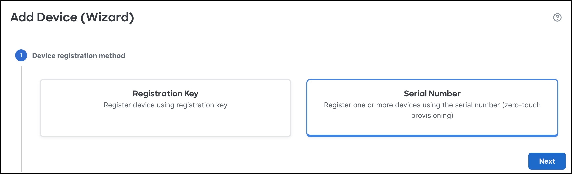
In Device registration method, click Serial Number and click Next.
4.
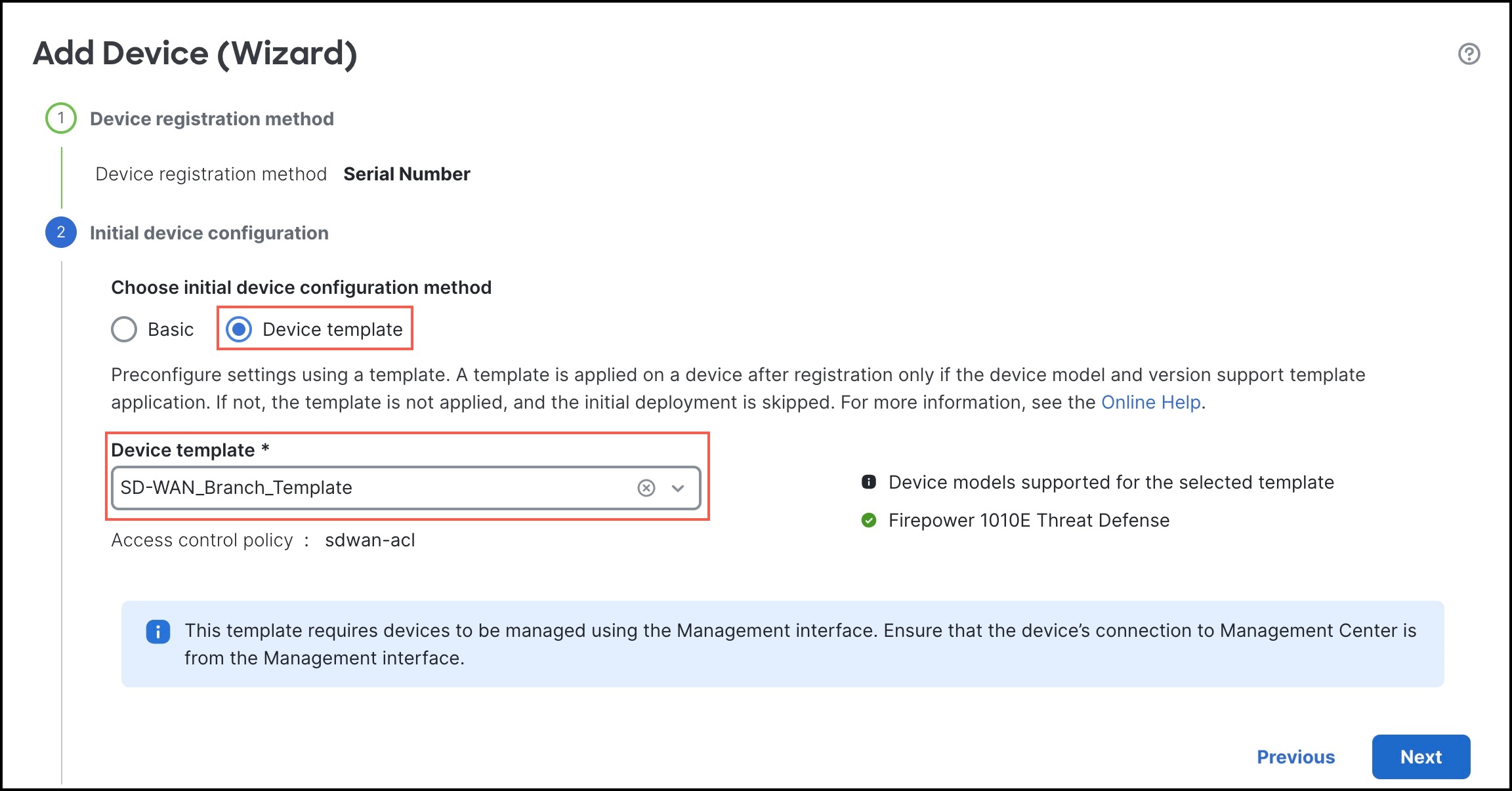
In Initial device configuration:
Click the Device template radio button.
From the Device template drop-down list, choose a device template for the device, and click Next.
5.
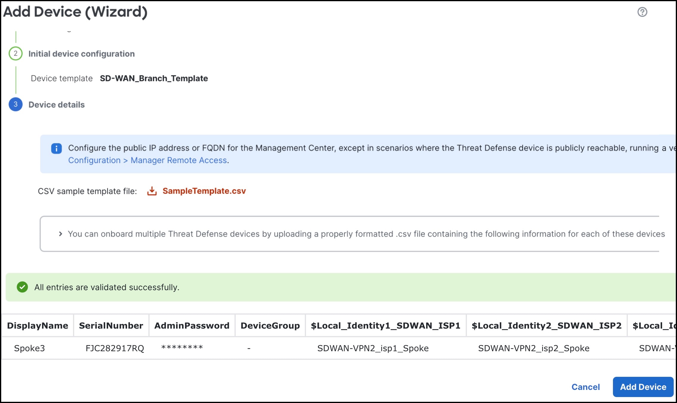
In Device details:
Download SampleTemplate.csv. This file includes parameters that must be defined for each device. For more information on the CSV template file parameters, see CSV Template File.
Drag & drop your CSV template file or click Browse to select the CSV template file that you want to upload. A validation check is done on the file after you upload it.
After the CSV template file has been uploaded successfully, the content of the CSV template file is displayed in a table format.
See the following sample CSV template file containing parameters for onboarding the Cisco Firepower 1120 Threat Defense device.
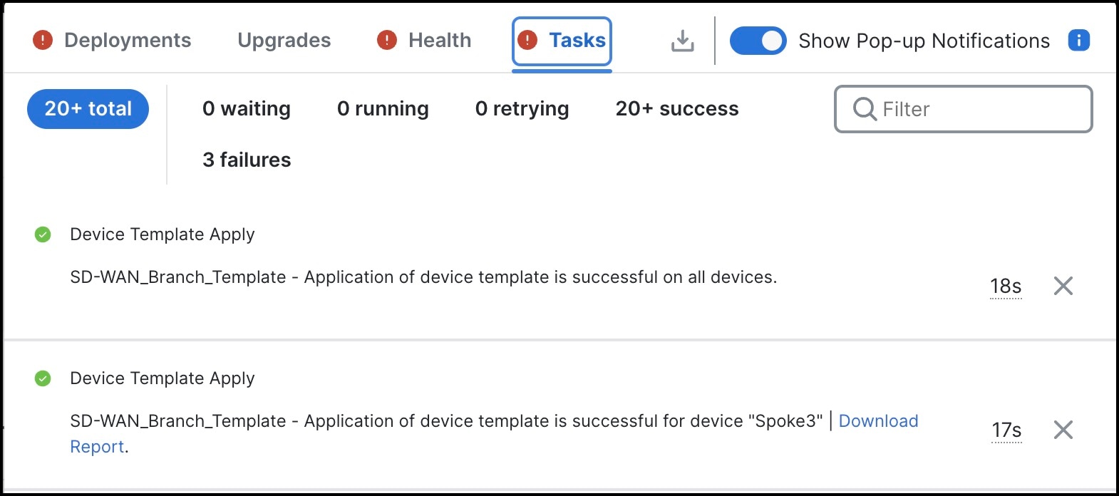
The template configurations are applied after the device is successfully registered with the Management Center.
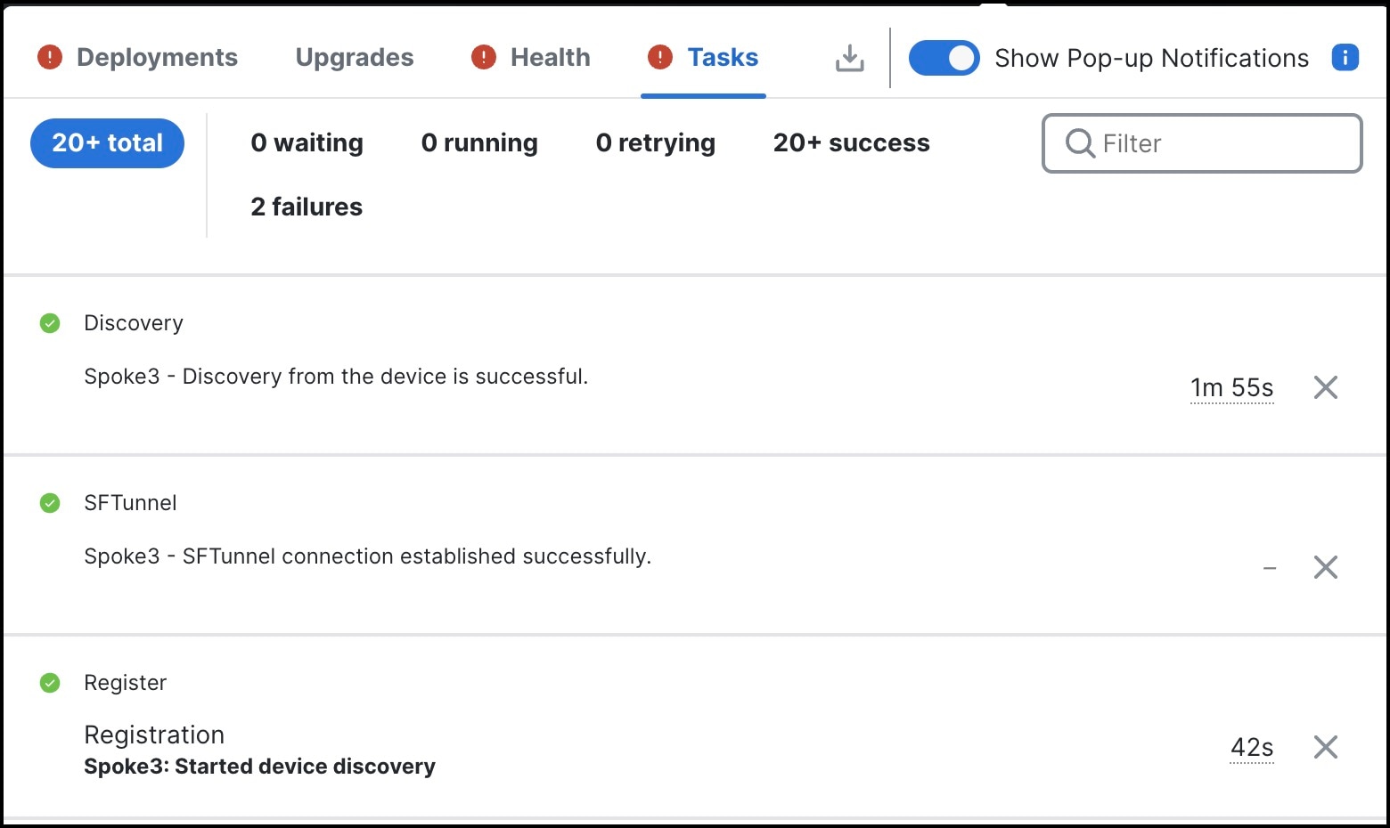
In the Notifications > Tasks window, you can view the messages related to the device registration, device discovery, and device template application.
A Device Template Apply report is generated after the apply template task is completed. This report is generated on both successful and unsuccessful application of the template on the device. You will see a link to this report in the Notifications > Tasks window.