Use Cases for SD-WAN Capabilities in Cisco Secure Firewall

PDF

Configure OSPF on the Spoke Node

Updated: February 5, 2026

Overview

Provides instructions for configuring OSPF on a Threat Defense (FTD) spoke to route traffic across a route-based site-to-site VPN using Firewall Management Center (FMC).

Procedure

1.

To edit the spoke node, choose Devices > Device Management and click the Edit (edit icon) icon for the NGFWBR1 node.

2.

In the Interfaces tab:

  • Verify the details of Tunnel1 interface that was created earlier in the spoke configuration.

  • Verify the details of the Loopback1 interface that was created earlier and serves as the IP address for Tunnel1.

3.

Click Routing.

4.

Click OSPF in the left panel.

5.

Check the Process 1 checkbox to enable an OSPF instance.

6.

Click the Area tab.

7.

Click +Add. The Add Area dialog box appears. Modify the following fields:

  • OSPF Process—Choose the process ID as 1.

  • Area ID—Ensure the value is 1.

    The rest of the fields use default values.

  • Available Network— To add networks to be advertised over the tunnel:

    • To add a new network object, click . Enter these details:

      • Name—enter the name as Spoke_Tunnel_IP.

      • Network—Select the Host option and enter the host IP as 169.254.20.1.

      • Click Save.

    • Enter Spoke in the search area of the Available Network field. The newly added network object ( Spoke_Tunnel_IP) is listed. Select the object and click Add to add it to the Selected Network list.

    • Enter Branch in the search area of the Available Network field. The Branch_LAN network object is listed. Select the object and click Add to add it to the Selected Network list.

  • Click OK.

A row is added in the Area tab.
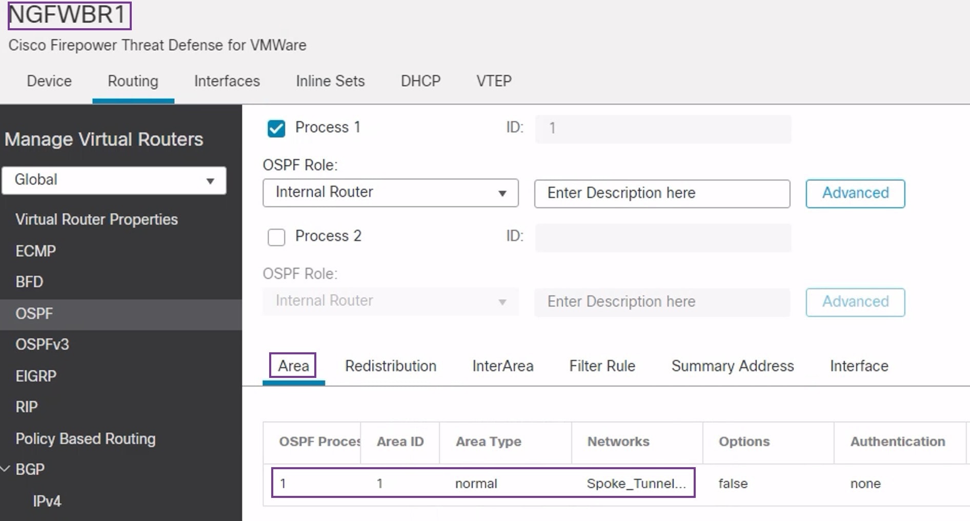
Screenshot of OSPF routing for a spoke device in Firewall Management Center
8.

Click Save to save the OSPF configuration for the spoke node.