Overview
Provides instructions for configuring a backup static VTI for spoke devices to maintain VPN connectivity with the hub and ensure continuous traffic flow.
Firewall Threat Defense supports the configuration of a backup tunnel for the route-based (VTI) VPN. When the primary VTI is unable to route the traffic, the traffic in the VPN is tunneled through the backup VTI.
Procedure
| 1. | Choose Devices > Site-to-site VPN to view the configured Corporate-VPN VPN topology and click the Edit ( |
|
| 2. | In the Spoke Nodes section, click the Edit ( |
|
| 3. | Click the Add Backup VTI link to add the secondary VTI tunnel. The link displays the Backup VTI section. 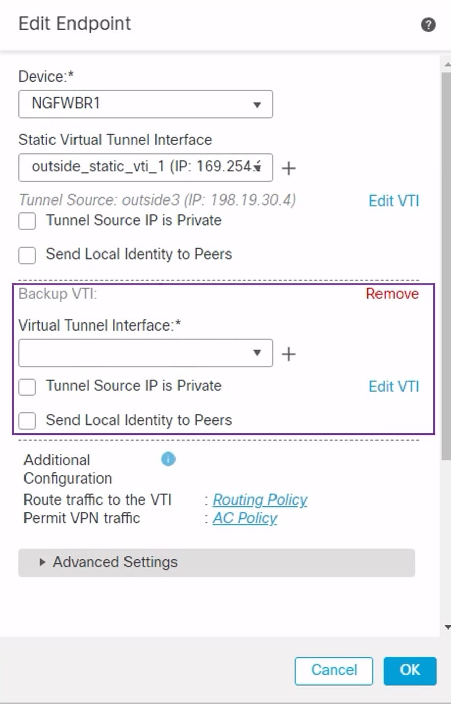
|
|
| 4. | Click + next to the Virtual Tunnel Interface drop-down list to add a new VTI. The Add Virtual Tunnel Interface dialog box appears with the following pre-populated default configurations.
Click OK to save the VTI. A message is displayed that confirms the VTI is created successfully. Click OK. The backup VTI Interface is set to outside_static_vti_2(169.254.20.1). |
|
| 5. | Click OK to save the spoke configuration. |
|
| 6. | Click Save to save the VPN topology. |
