Overview
Provides instructions to verify routing and state of primary and secondary DVTI VPN tunnels between hub and spoke devices in Firewall Management Center (FMC).
Verify that both the primary and secondary VTI tunnels between the branch node and the hub node are configured, up, and active.
-
Verify Tunnel Status on the Site-to-site VPN Dashboard
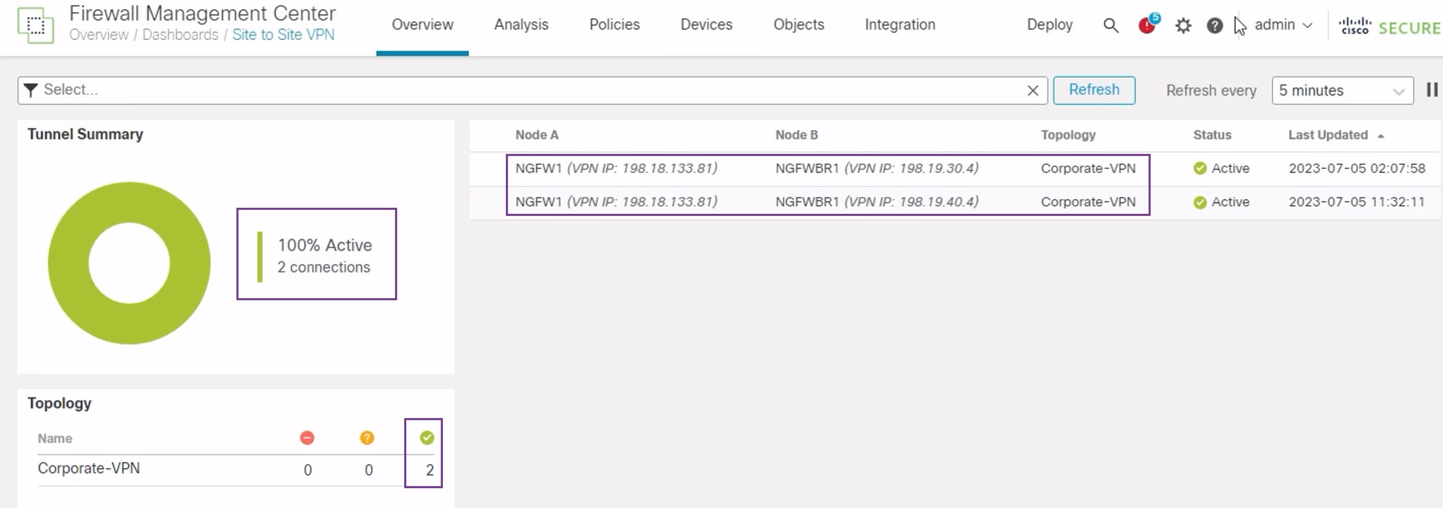
To verify that the VPN tunnel is up and green, choose Overview > Dashboards > Site-to-site VPN.
-
Verify Routing on the Hub and Branch Nodes
-
Choose Devices > Device Management.
-
To edit NGFW1, click the Edit icon.
-
Click the Device tab.
-
Click the CLI button in the General card. The CLI Troubleshoot window appears
-
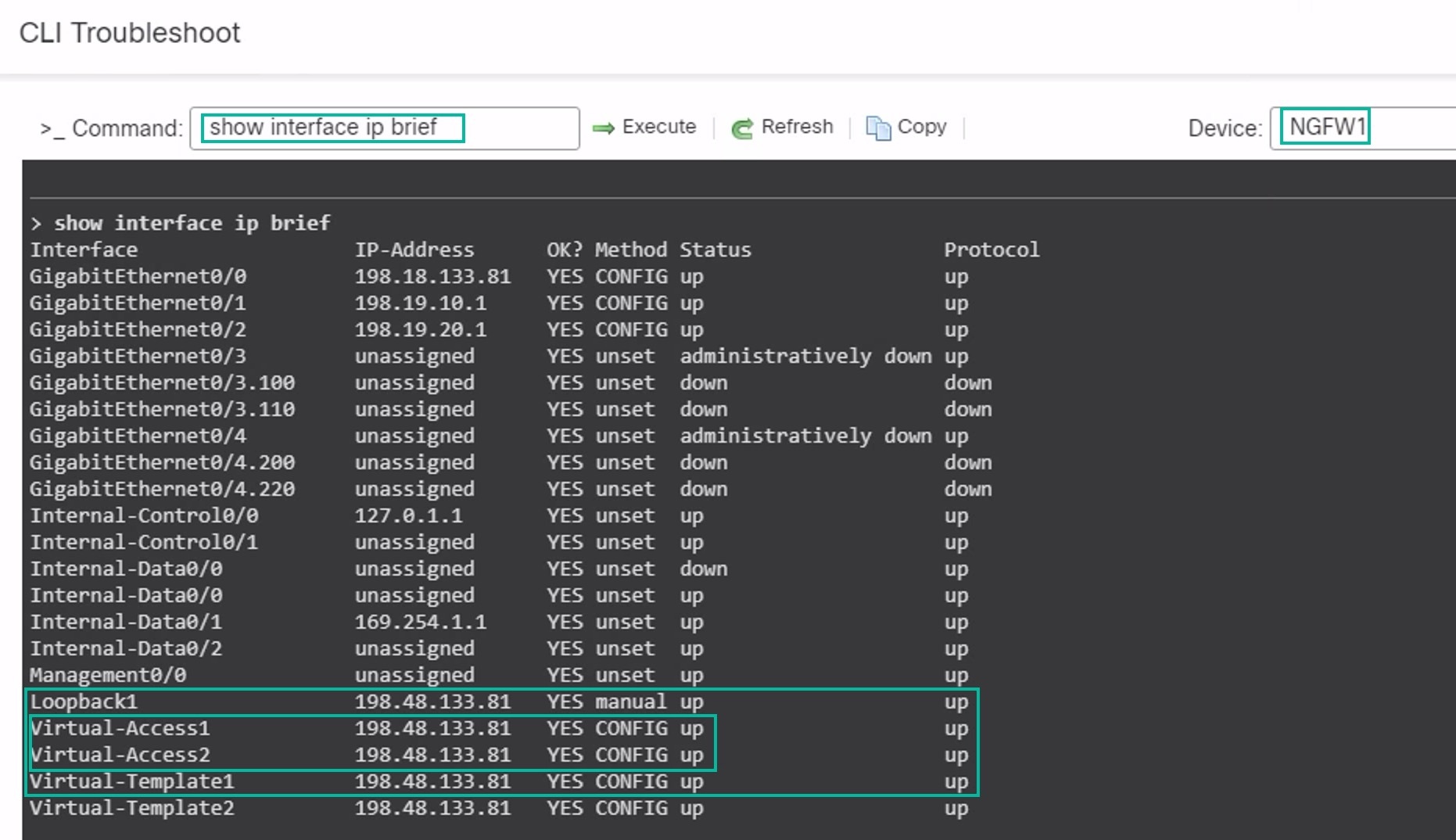
Enter show interface ip brief in the Command field and click Execute to view the dynamic Virtual Access interfaces that were created from the DVTI on the hub.
The Virtual-Access2 interface gets generated from the same DVTI when NGFWBR1 connects to NGFW1 over the secondary VTI connection.
-
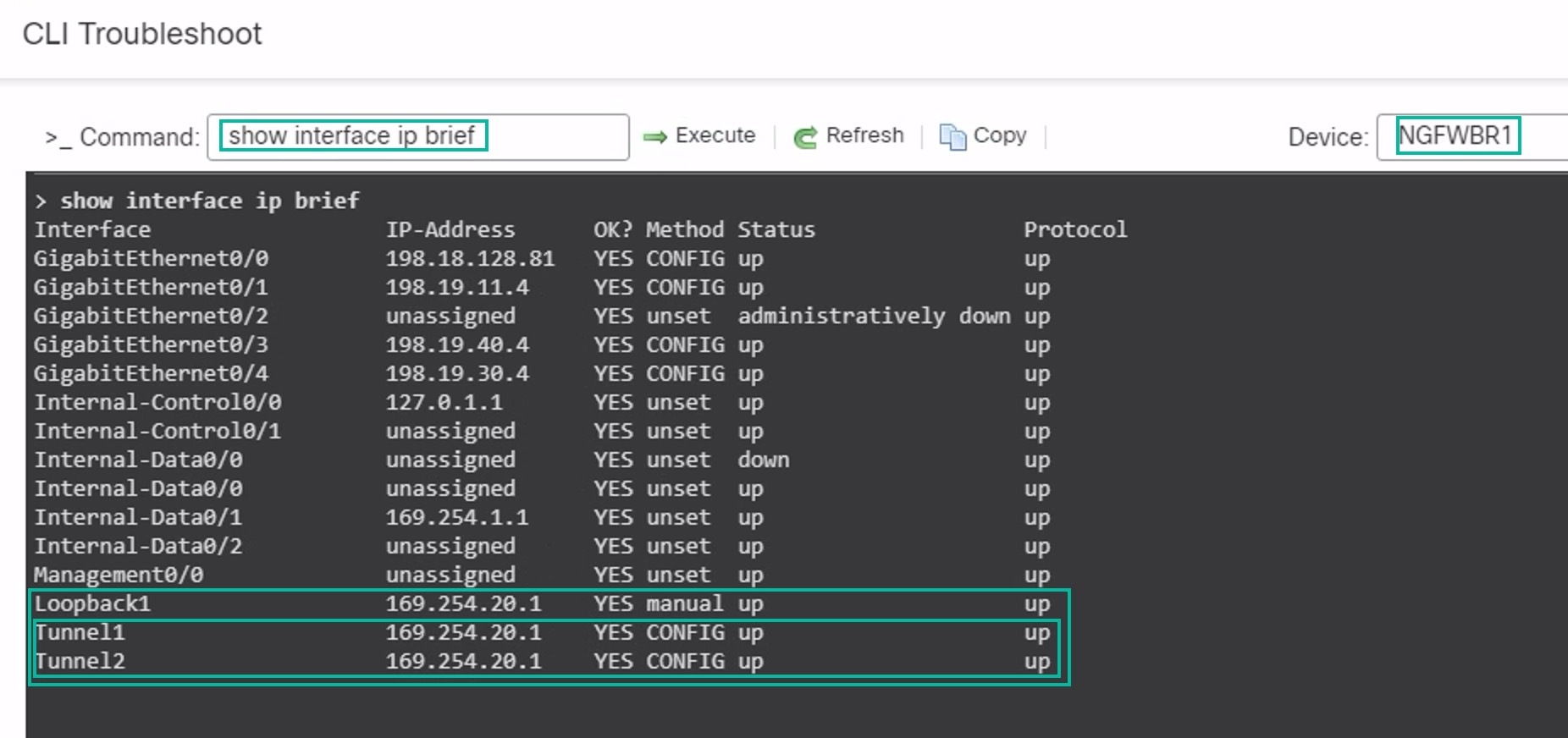
Repeat Steps 2 through 5 for the NGFWBR1 node to view the static VTI interfaces Tunnel1 and Tunnel2 as shown in the figure below.
-
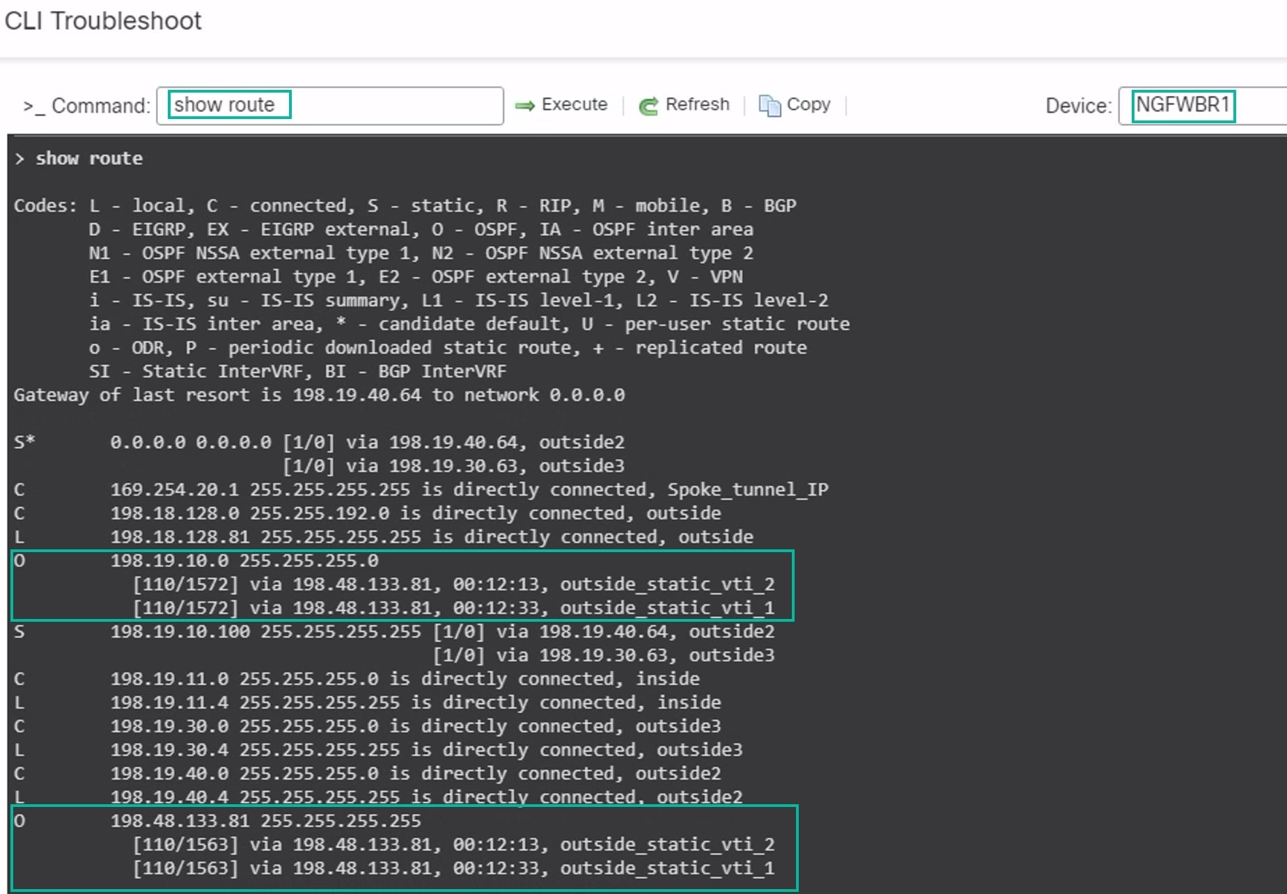
Enter show route in the Command field and click Execute to view the routes after the addition of the secondary VTI tunnel.
-
Note that the Corporate_LAN (198.19.10.0/24) has been learnt over OSPF on both the primary (outside_static_vti_1) and secondary (outside_static_vti_2) VTIs.
-
Note that the DVTI Tunnel IP (198.48.133.81) has also been learnt over OSPF on both the primary and secondary VTIs.
-
-
-
Verify Failover to Secondary Tunnel When the Primary Tunnel Goes Down
-
In this example, to validate failover to the secondary tunnel, packet loss can be induced by restricting outbound traffic sourced from the outside3 interface going to internet either through an access control list on the upstream device or by shutting down the outside3 interface for threat defense from the management center.
Shutting down an interface is network intrusive and must not be tried in a production network.
-
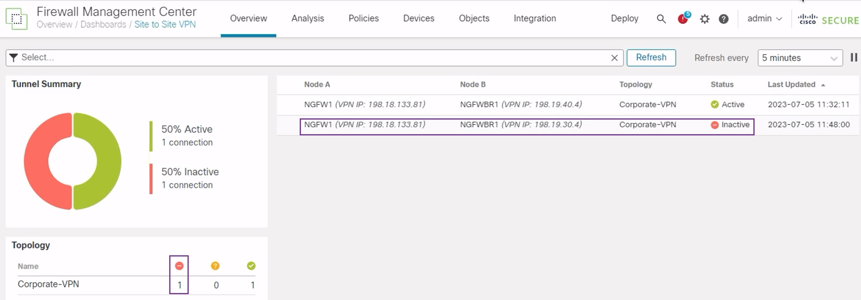
In the Site-to-site VPN Dashboard, the primary tunnel is down as shown in the figure below.
-
Initiate traffic from Branch to Hub. Log in to the WKST BR workstation and SSH to the host behind NGFW1. Ensure that you are able to SSH successfully to the host.
-
Verify the egress path of the traffic using the Unified Event Viewer:
-
Choose Analysis > Unified Events.
-
Add the VPN Action, Encrypt Peer, Decrypt Peer, and Egress Interface columns using the column picker.
-
Reorder and resize the new columns along with the columns, Destination Port/ICMP Code, Access Control Rule, Access Control Policy, and Device as seen in the figure below.
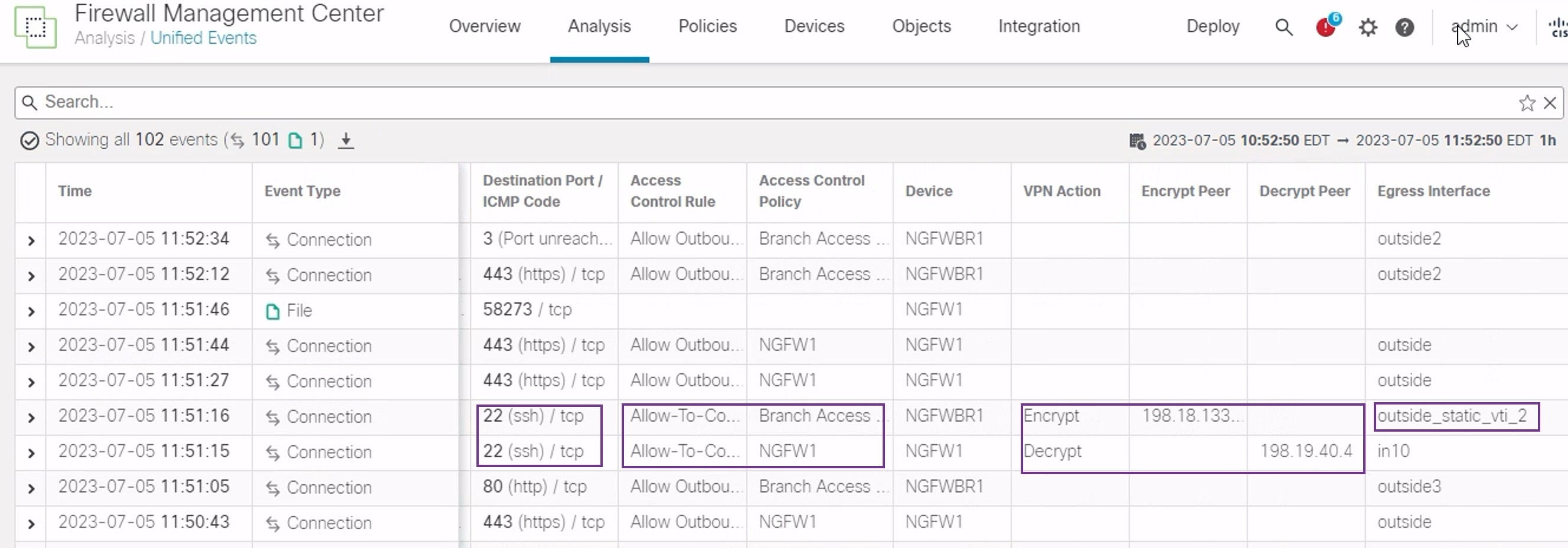
Notice that the egress interface on the NGFWBR1 for the SSH (Port 22) is now displayed as the secondary interface (outside_static_vti_2).
-
-