Overview
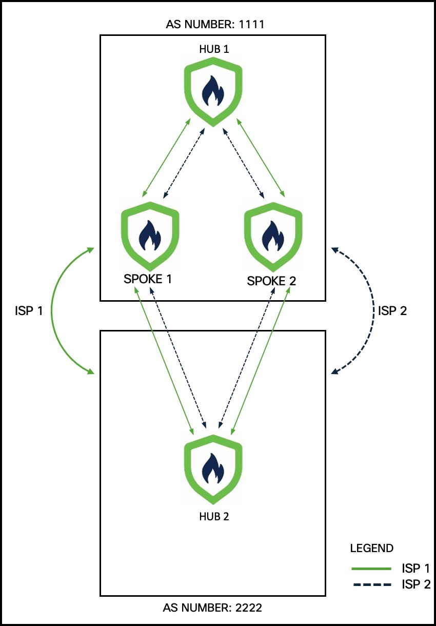
Illustrates a sample dual ISP network topology with branch devices connecting over dual ISP links and integrating with Firewall Management Center (FMC).
In the following sample dual-ISP topology, the hubs are in different regions. The hubs and spokes use External Border Gateway Protocol (eBGP) as the routing protocol to exchange routing information.
-
Hub 1 is a Firewall Threat Defense hub device in a branch office with autonomous system (AS) number as 1111.
-
Hub 2 is a Firewall Threat Defense hub device in a branch office with AS number as 2222.
-
Spoke 1 and Spoke 2 are Firewall Threat Defense spoke devices in the branch with AS number as 1111.
-
outside-isp1 is the VPN interface of each spoke to ISP 1.
-
outside-isp2 is the VPN interface of each spoke to ISP 2.
Alex aims to onboard a Cisco Secure Firewall 1210CE Firewall Threat Defense device into an existing dual-ISP SD-WAN topology using the device's serial number and the preconfigured settings. Utilizing the new intuitive SD-WAN VPN wizard and device templates, he can efficiently create SD-WAN VPN topologies and streamline the onboarding process for the device in the SD-WAN topology. In our example, this device is Spoke 3.
The topology has the following parameters:
| Device | Management IP Address | Inside Interface | Outside Interface |
|---|---|---|---|
| Hub1 | 209.165.200.225 | 198.51.100.17/28 |
|
| Hub2 | 209.165.200.226 | 198.51.100.33/28 |
|
| Spoke 1 | 209.165.200.227 | 198.51.100.65/28 |
|
| Spoke 2 | 209.165.200.228 | 198.51.100.129/28 |
|
| Device | Hub Loopback IP Addresses | IP Address Pools |
|---|---|---|
| Hub1 |
|
|
| Hub2 |
|
|
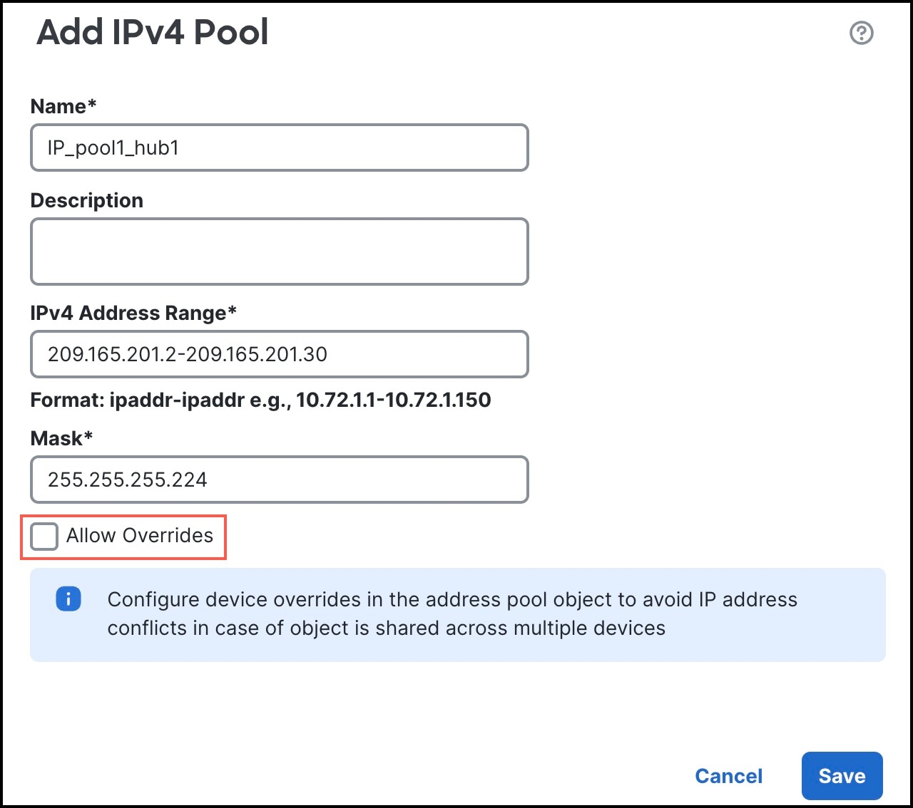
Note that when you configure the hub IP address pools, ensure that you do not check the Allow Overrides check box in the Add IPv4/IPv6 Pool dialog box (Objects > Object Management > Address Pools). You can also create these address pools in the SD-WAN wizard.