Configuration Guide for Cisco NCS 1014, IOS XR Releases 26.x.x

PDF

Configuration Guide for Cisco NCS 1014, IOS XR Releases 26.x.x

Channel APC

Want to summarize with AI?

Log in

This section explains how Channel APC regulate optical channels to maintain consistent power spectral density before transmission.


From Release 25.2.1, Channel APC is supported on the EDFA2 card. It is an optical application that maintains all optical channels at a consistent Power Spectral Density (PSD) target by dynamically regulating optical components. This ensures a flat spectrum before transmission over the fiber span.

The purpose of the Channel APC control loop is to equalize the Power Spectral Density (PSD) of all channels to a defined Channel Target PSD.

  • Channel Target PSD:

    This is an optical-line-control (OLC) configuration parameter that defines the desired PSD level for all channels. By default, this value is –20 dBm, measured in dBm/12.5GHz.

  • Optical Channel Monitor (OCM):

    The OCM device provides readings of the channel power spectral density, dividing the spectrum into 6.25GHz slices. The Channel PSD is calculated based on readings from the OCM and is averaged over the central 25GHz bandwidth.

  • Input Channel Acceptance:

    Before a channel is transmitted, its input PSD is evaluated against the Channel PSD target plus a defined margin (PSD_MARGIN). A channel is accepted and unblocked by the Wavelength Blocker (WB) if its estimated PSD after initial amplification and WB insertion loss is greater than the target PSD plus the margin.

  • PSD Control Loop:

    Once a channel is accepted, the WB attenuation for the channel's slices is adjusted from maximum to an initial value calculated to bring the Channel PSD near or slightly below the target. The control loop then periodically monitors the Channel PSD at the WB output. If the discrepancy between the measured PSD and the target PSD exceeds a defined threshold (PSD Correction Tolerance), the WB attenuation is corrected incrementally. The loop continues until the discrepancy is small, applying a final correction equal to the residual error. The loop regulates again if the discrepancy later exceeds the threshold.

This diagram shows the NCS1K14-EDFA2 line card optical layout. Optical components controlled by channel APC are highlighted in green.
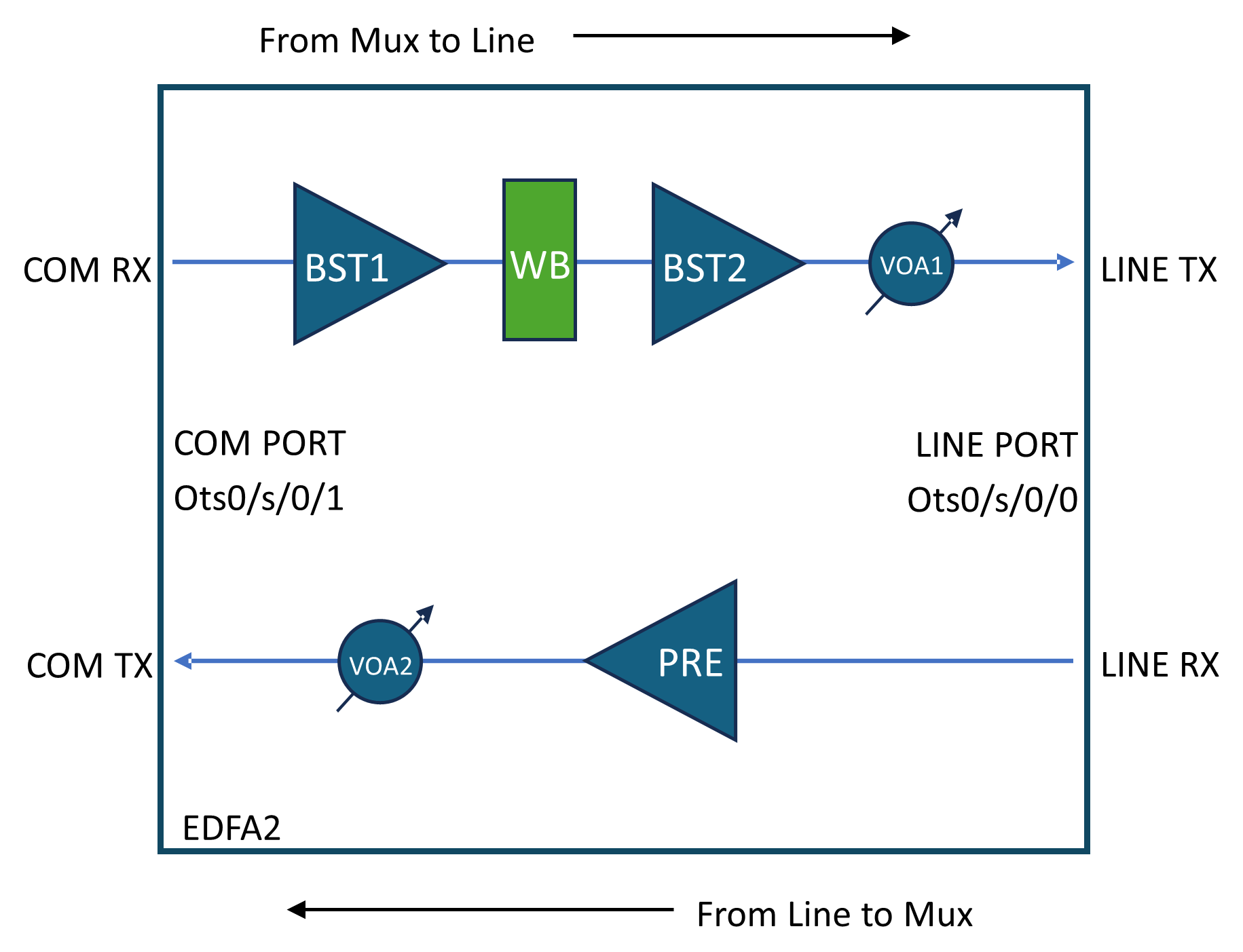
Figure 1. NCS1K14-EDFA2 line card optical layout
NCS1K14-EDFA2 line card optical layout

Channel Acceptance and Blocking Criteria

  • Acceptance:
    • By default, WB blocks all C-band spectrum.

    • Channels must have PSD after WB (0 attenuation) higher than the target PSD plus a 0.5 dBm/12.5 GHz margin to be accepted.

  • Blocking:
    • Channels with WB attenuation at 0 dB and PSD lower than target PSD minus 2.0 dBm/12.5 GHz tolerance are blocked by the control loop.


How channel APC works

Summary

Channel APC control loop equalizes the Power Spectral Density (PSD) of all channels to a defined Channel Target PSD.

Workflow

These stages describe channel APC process:

  1. Input and Amplification:
    • Channels enter via Controller Ots0/<slot>/0/1 (COM-RX).
    • First stage amplification by BST1.
    • Channel APC equalizes PSD across channels before the second stage amplifier (BST2 + VOA1).
  2. Wavelength Blocker (WB):
    • Controls attenuation per 6.25 GHz slice (0 to 15 dB or full block).
    • Channel power equalization is based on a configurable Channel Target PSD (default: -20 dBm/12.5 GHz).
    • PSD is averaged over the central 25 GHz bandwidth from OCM measurements.
  3. Channel APC Control:
    • When enabled, Channel APC overrides manual WB attenuation settings.
    • OSC channel is excluded from Channel APC control.

Enable channel APC

This topic describes how to enable channel APC.

This task describes how to configure channel APC. This configuration is in this topic:

  • Enable channel APC

Procedure

Use the following commands to enable channel APC:

configure
optical-line-control
controller ots <Rack/Slot/Instance/Port>
channel-apc flat-psd-eq-mode
commit
end

Disable channel APC

This topic describes how to disable channel APC.

This task describes how to configure channel APC. This configuration is in this topic:

  • Disable channel APC

Procedure

Use the following commands to disable channel APC:

configure
optical-line-control
controller ots <Rack/Slot/Instance/Port>
no channel-apc flat-psd-eq-mode
commit
end

Pause channel APC

This topic describes how to pause channel APC.

This task describes how to configure channel APC. This configuration is in this topic:

  • Pause channel APC

Procedure

Use the following commands to pause channel APC:

configure
optical-line-control
controller ots <Rack/Slot/Instance/Port>
channel-apc-pause
commit
end

Resume channel APC

This topic describes how to resume channel APC.

This task describes how to configure channel APC. This configuration is in this topic:

  • Resume channel APC

Procedure

Use the following commands to resume channel APC:

configure
optical-line-control
controller ots <Rack/Slot/Instance/Port>
no channel-apc-pause
commit
end

Set target PSD for channel APC

This topic describes how to set target PSD for channel APC.

This task describes how to configure channel APC. This configuration is in this topic:

  • Set target PSD for chanel

Procedure

Use the following commands to set target PSD for a channel:

configure
optical-line-control
controller ots <Rack/Slot/Instance/Port>
psd-target <value in dBm/12.5GHz>
commit
end

Example:

This sample configuration sets the target PSD to -22 dBm/12.5 GHz:

configure
optical-line-control
controller ots 0/0/0/0
psd-target -220
commit
end

Configure input amplifier

This topic describes how to configure channel APC.

In scenarios with low total input power, you must adjust BST1 amplifier gain and range. This table shows some typical scenarios:

Table 1. BST1 Amplifier Configuration
Optical Interfaces Spacing BST1 Total Input Power [dBm] BST1 range BST1 Gain [dB]
400ZR 75 GHz 0.2~2.3 Extended 18.5
mix 400ZR/800ZR 75/150 GHz -5~0.2 Extended 18.5
800ZR 150 GHz 0.6~1.2 Extended 18.5
DCI 75 GHz 6~6.9 Normal 8
mix DCI/DCI-1 75/150 GHz 5.3~6.9 Normal 8
DCI-1 150 GHz 9.8~10.4 Normal 8
DCI-2 (CIM8) 150 GHz 11.4~12.2 Normal 8

Procedure

Use the following commands to adjust BST1 amplifier gain and gain range:

configure
controller ots <Rack/Slot/Instance/Port>
ingress-ampli-gain-range <normal|extended>
ingress-ampli-gain <gain_value_in_tenths_of_dB>
commit
end

Example:

This sample configuration sets BST1 gain range to extended and the gain to 19.5 dB:

configure
controller ots 0/0/0/1
ingress-ampli-gain-range extended
ingress-ampli-gain 195
commit
end