Configuration Guide for Cisco NCS 1014, IOS XR Releases 26.x.x

PDF

Idle Insertion for Ethernet controllers

Want to summarize with AI?

Log in

This section explains how idle insertion enables pre-traffic link verification and fault isolation between high-speed Ethernet controllers.


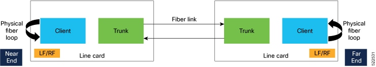
Idle insertion for Ethernet controllers feature allows you to perform end-to-end link verification between 100GE or 400GE or or 800GE Ethernet controllers before bringing up the actual traffic. This feature enables you to perform pre-provisioning checks to isolate link errors in advance without any Ethernet testers.

Table 1. Feature history

Feature name

Release information

Feature description

Idle frame insertion on the 800GE Ethernet client

Cisco IOS XR Release 26.2.1

This feature allows you to insert idle frames in either the ingress or egress direction on the 800GE Ethernet client controller of the 2.4T, 2.4TX, and 2.4TA line cards. Idle frame insertion is configured per controller and direction using the commands insert-idle ingress or insert-idle egress under the 800GE Ethernet controller configuration mode.

This feature support end-to-end link verification and fault isolation between Ethernet controllers before actual traffic is transmitted.

Note

OTU4 client rate is not supported.

Idle frames can be inserted in both the ingress and egress directions on Ethernet controllers and the LOCAL-FAULT and REMOTE-FAULT alarms are cleared. The performance monitoring counters on the pcs layer are monitored to check for any errors on the link.

Note

Do not configure the Idle insertion for Ethernet controllers feature on the link that carries live traffic.


This diagram describes the recommended topology for link verification.

Figure 1. Topology for link verification
Topology for Link Verification

These steps describe the sequence for link verification using this topology:

  1. Both the near-end and far-end clients have the LOCAL-FAULT alarm if the trunk is up on both the ends.

  2. Enable idle ingress on the near-end client. The idle frame transmits toward the trunk link and reaches the far-end client. The LOCAL-FAULT alarm is then cleared on the far-end client.

  3. As the far-end client has fiber loop, the idle frame is inserted again into the same client RX toward the trunk link and reaches the near-end client. The LOCAL-FAULT alarm is then cleared on the near-end client as well.

  4. When you enable idle insertion on any client and in any direction, the idle frame transmits in loop similar to this topology and all the LOCAL-FAULT and the REMOTE-FAULT alarms are cleared.

  5. The link can be monitored after all the alarms are cleared. The link has a problem if any alarm is reported during the link test.


Configure idle insertion on Ethernet controllers

Use this task to configure or disable idle insertion on Ethernet controllers.

Note

Do not configure idle frame insertion with hold-off timer.

Procedure

1.

Run the controller eightHundredGigECtrlrRack/Slot/Instance/Port/insert-idle ingressinsert-idle egress command to enable this feature.

Example:

This is a sample for enabling the idle ingress and idle egress in 800GE controllers.


RP/0/RP0/CPU0:ios#configure
RP/0/RP0/CPU0:ios(config)#controller eightHundredGigECtrlr 0/1/0/2 ​
RP/0/RP0/CPU0:ios(config-eth-ctrlr)#insert-idle ingress
RP/0/RP0/CPU0:ios(config-eth-ctrlr)#commit
RP/0/RP0/CPU0:ios(config-eth-ctrlr)#end

Example:

This is a sample for enabling the idle ingress and idle egress in 100GE controllers.


RP/0/RP0/CPU0:ios#configure
RP/0/RP0/CPU0:ios(config)#controller hundredGigECtrlr 0/2/0/2
RP/0/RP0/CPU0:ios(config-eth-ctrlr)#insert-idle ingress
RP/0/RP0/CPU0:ios(config-eth-ctrlr)#insert-idle egress
RP/0/RP0/CPU0:ios(config-eth-ctrlr)#commit
RP/0/RP0/CPU0:ios(config-eth-ctrlr)#end
2.

Run the controller eightHundredGigECtrlrRack/Slot/Instance/Portno insert-idle ingressno insert-idle egress command to disable this feature.

After disabling the idle frame insertion feature, the LOCAL-FAULT or REMOTE-FAULT alarm may not appear again because the idle frames are in loop. Hence, you must break the idle frame loop in the link by performing either one of the following.

These are the limitations:

  • Perform fiber OIR on either the near-end or far-end client port.

  • Perform shut and unshut operation on any client port.


Verify idle insertion configuration for Ethernet controllers

Use this task to verify idle insertion for Ethernet controllers.

Note

Do not configure idle frame insertion with hold-off timer.

Procedure

Run the show controller eightHundredGigECtrlrRack/Slot/Instance/Port command to verify the idle ingress and idle egress that is configured on the Ethernet controllers of a 1.2T card.

Example:

This is a sample to verify idle insertion for 800GE controllers.

RP/0/RP0/CPU0:ios#show controllers EightHundredGigECtrlr 0/1/0/2 
Fri Jun  5 12:49:59.638 IST
Operational data for interface EightHundredGigECtrlr0/1/0/2:
State:
    Administrative state: enabled
    Operational state: Up
    LED state: Green On
    Maintenance: Disabled
    AINS Soak: None
      Total Duration: 0 hour(s) 0 minute(s)
      Remaining Duration: 0 hour(s) 0 minute(s) 0 second(s)
    Laser Squelch: Disabled
    Insert Idle Ingress: Enabled
    Insert Idle Egress: Disabled
    Last link flapped: 00:00:25
Phy:
    Media type: Not known
    Statistics:
        FEC:
            Corrected Codeword Count: 496226                   Valid: True       Start time: 12:48:06 Fri Jun 05 2026
            Uncorrected Codeword Count: 0                      Valid: True       Start time: 12:48:06 Fri Jun 05 2026
        PCS:
            Total BIP errors: 0                                Valid: True       Start time: 12:48:06 Fri Jun 05 2026
            Total frame errors: 0                              Valid: False      Start time: 12:48:06 Fri Jun 05 2026
            Total Bad SH: 0                                    Valid: False      Start time: 12:48:06 Fri Jun 05 2026
Autonegotiation disabled.
Operational values:
    Speed: 800Gbps
    Duplex: Full Duplex
    Flowcontrol: None
    Loopback: None (or external)
    Pre FEC BER: 1.9E-08
    Post FEC BER: 0.0E+00
    Forward error correction: Standard (Reed-Solomon)
    Holdoff Time: 0ms
 

Example:

This is a sample to verify idle insertion for 100GE controllers.

RP/0/RP0/CPU0:ios#show controllers hundredGigECtrlr 0/2/0/2
Wed Mar 30 06:56:58.878 UTC
Operational data for interface HundredGigECtrlr0/2/0/2:
State:
    Administrative state: enabled
    Operational state: Up
    LED state: Green On
    Maintenance: Disabled
    AINS Soak: None
      Total Duration: 0 hour(s) 0 minute(s)
      Remaining Duration: 0 hour(s) 0 minute(s) 0 second(s)
    Laser Squelch: Disabled
    
    Insert Idle Ingress: Enabled
    Insert Idle Egress: Enabled
    
Phy:
    Media type: Not known
    Statistics:
        FEC:
            Corrected Codeword Count: 0
            Uncorrected Codeword Count: 0
Autonegotiation disabled.
Operational values:
    Speed: 100Gbps
    Duplex: Full Duplex
    Flowcontrol: None
    Loopback: None (or external)
    BER monitoring:
        Not supported
    Forward error correction: Standard (Reed-Solomon)
    Holdoff Time: 0ms