Configuration Guide for Cisco NCS 1014, IOS XR Releases 26.x.x

PDF

Configuration Guide for Cisco NCS 1014, IOS XR Releases 26.x.x

Laser squelching

Want to summarize with AI?

Log in

This section explains how laser squelch mechanisms operate on Ethernet controllers, their benefits in fault handling, and the differences across card types.


You can enable laser squelching on Ethernet controllers. Laser squelching can be enabled on QXP, 1.2T, 2.4T, and 2.4T-X cards which shuts down the laser in the event of trunk faults (LOS, LOF), and a SQUELCHED alarm is raised on the mapped client port.

Laser squelching uses an interrupt based method. Therefore, squelching occurs faster than in previous releases.

Beyond trunk faults, squelching occurs for these client alarms:

  • 1.2T cards: LF, LOA, and CSF (ingress only)

  • 2.4T and 2.4T-X cards: LF, LOA, CSF, and AIS (ingress only)

Configure laser squelching

Enable or disable the laser squelch feature for specific optical cards, enhancing operational control and safety.

Laser squelch disables the laser output on designated ports/faults to prevent unwanted signal transmission during error conditions or maintenance.

Procedure

1.

Configure laser squelching for the desired card type:

For 1.2T cards, enter controller HundredGigECtrlr Rack/Slot/Instance/Port/Lane laser-squelch command.

For 2.4T or 2.4TX cards, enter controller fourHundredGigECtrlr Rack/Slot/Instance/Port/Lane laser-squelch command.

Example:

This is a sample where laser squelching is enabled on the Ethernet controller of a 2.4T card and a 2.4TX card.


RP/0/RP0/CPU0:ios#configure
RP/0/RP0/CPU0:ios(config)#controller fourHundredGigECtrlr 0/1/0/1
RP/0/RP0/CPU0:ios(config-eth-ctrlr)#laser-squelch
RP/0/RP0/CPU0:ios(config-eth-ctrlr)#commit

This is a sample to view the laser squelch status on the controller of a 2.4T card and a 2.4TX card.

Example:

Note

In case of muxponder configuration on the 2.4T-X card, and if laser squelch is configured on the split port, whenever a fault is received on any one trunk, the corresponding split port will be squelched.

2.

Verify the laser squelch status on the controller of a 2.4T card or a 2.4TX card.

Example:


RP/0/RP0/CPU0:ios#show controllers fourHundredGigEctrlr 0/0/0/4
Fri Nov 17 14:26:43.213 UTC
Operational data for interface FourHundredGigECtrlr0/0/0/4:

State:
    Administrative state: enabled
    Operational state: Up
    LED state: Green On
    Maintenance: Disabled
    AINS Soak: Running
      Total Duration: 0 hour(s) 5 minute(s)
      Remaining Duration: 0 hour(s) 3 minute(s) 34 second(s)
    Laser Squelch: Enabled
    Insert Idle Ingress: Disabled
    Insert Idle Egress: Disabled

Phy:
    Media type: Not known
    Statistics:
        FEC:
            Corrected Codeword Count: 580070472                Valid: False      Start time: 13:12:29 Fri Nov 17 2023
            Uncorrected Codeword Count: 0                      Valid: False      Start time: 13:12:29 Fri Nov 17 2023
        PCS:
            Total BIP errors: 0                                Valid: False      Start time: 13:12:29 Fri Nov 17 2023
            Total frame errors: 0                              Valid: False      Start time: 13:12:29 Fri Nov 17 2023
            Total Bad SH: 0                                    Valid: False      Start time: 13:12:29 Fri Nov 17 2023

Autonegotiation disabled.

Operational values:
    Speed: 400Gbps
    Duplex: Full Duplex
    Flowcontrol: None
    Loopback: None (or external)
    BER monitoring:
        Not supported
    Forward error correction: Standard (Reed-Solomon)
    Holdoff Time: 0ms
Laser squelching is enabled on the specified optical card(s). The system disables laser output in response to faults or based on maintenance needs.

Protection switching use cases for Fast-Squelching

Table 1. Feature History

Feature Name

Release Information

Description

Client side PSM support for NCS1K14-2.4T-K9 and NCS1K14-2.4T-X-K9 cards configured with fast -squelching

Cisco IOS-XR Release 26.2.1

In addition to the NCS1K4-1.2T-K9 cards, now protection switching is supported on NCS1K14-2.4T-K9, and NCS1K14-2.4T-X-K9 cards with the client pluggables QDD-400G-FR4-S and the QDD-400G-LR4-S pluggables that are configured with fast-squelching.

The supported datapath configurations for NCS1K14-2.4T-K9 and NCS1K14-2.4T-X-K9 cards include:

  • Slice mode (only for 400GE client rate)

  • Bundle mode configuration

This update enhances network reliability by providing automated failover and signal protection for 2.4T and 2.4T-X cards, ensuring consistent uptime for high-bandwidth services.

When implementing protection switching in NCS 1014 deployments that have Fast-Squelching configured, fast-squelching increases protection switching speed during trunk or client faults.

From Release 26.2.1, protection switching is supported on NCS1K14-2.4T-K9 and NCS1K14-2.4T-X-K9 cards in addition to the NCS1K4-1.2T-K9 cards, for the QDD-400G-FR4-S and the QDD-400G-LR4-S pluggables.

The supported datapath configurations for 2.4T and 2.4T-X cards include:

  • Slice mode (only for 400GE client rate)

  • Bundle mode configuration

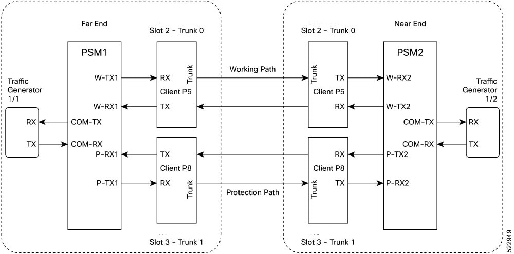
This sample topology includes a Far End station (FE station) and a Near End station (NE station). Each station includes an NCS 1014 node with two line cards. The nodes are connected to the respective traffic generators through a Protection Switching Module (PSM).

Figure 1. Reference topology for protection Switching

Protection switching principle (Trunk fault)

If there is a fiber cut in the trunk working path from the FE station to the NE station, an LOS alarm is raised on the NE working trunk. This results in the squelching of all client ports mapped to the working NE trunk port. As the laser of the client port is squelched, LOS is reported on the W-RX2 port of the PSM2. As the received optical power on the W-RX2 port of PSM is below the threshold, PSM2 switches to receive the optical signal in the P-RX2 port instead of the W-RX2 port. Hence switching happens for traffic from work to protect in FE station to NE station direction.

In the case of a unidirectional trunk fault, switching happens in one direction as explained above. In the other direction, when LOS is received at the W-RX2 port of PSM2, W-TX2 sends LOS for 25 milliseconds. When LOS is reported on the NE client port, fault gets propagated over the trunk, resulting in the squelching of FE station client ports. Finally, the LOS on the PSM port results in switching in this direction as well. In this way, bidirectional switching is implemented.

Protection switching principle (Client fault)

When a client failure happens on the FE station, a Client Signal Failure (CSF) alarm is raised on the NE station trunk. The CSF on the trunk results in the squelching of the corresponding client port, and the PSM switching happens. In summary, a fault on the NE station client RX port results in CSF on the FE station trunk, and the switching happens. And, a fault on the NE station client TX port results in LOS on the PSM ports, and the switching happens.

Guidelines and limitations:
  • The QDD-400G FR4-S and the QDD-400G-LR4-S client pluggables do not support switching from the active path to the protection path within 50 milliseconds.

    Note

    According to the QDD pluggable standard, if an electrical (TP1) or optical (TP3) signal is interrupted or disturbed at a client pluggable, and the Clock and Data Recovery (CDR) inside the QDD loses the lock, the QDD pluggable requires some time to recover the signal. Hence, when a fault is identified on the trunk port, the client port Rx loses the lock. The recovery takes between 1.5 and 2 seconds, depending on the pluggable standard.

  • PSM must be in the standalone mode.

  • PSM alarm threshold must be set to +/ –3 dBm from the actual power received in the PSM RX port.

  • If line card protection is required, the working and protect path must be configured in two different line cards.

  • If only client protection is required, the working and protection path can be configured in the same line card.

  • If the LC trunk configuration is x50 rate, then you cannot use a single line card for work and protection due to x50 coupled mode limitations (coupled trunk). This limitation applies only to 1.2T card..

  • Manual switch, force switch, and lock-out protection on PSM result in bidirectional switching.