Configuration Guide for Cisco NCS 1014, IOS XR Releases 26.x.x

PDF

Loop-and-drop mechanism on coherentDSP controller

Want to summarize with AI?

Log in

This section explains the loop-and-drop mechanisms on coherentDSP controllers and how they replace previous loop-and-continue mechanisms to enhance network fault indications.


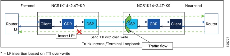
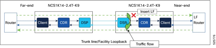
From Release 25.3.1, configuring trunk loopback on coherentDSP controllers activates a loop-and-drop mechanism, replacing the previous loop-and-continue mechanism. When you set up internal and line loopbacks under coherentDSP controller, these loopback types are automatically applied for the traffic:

  • Internal

  • Line

Table 1. Feature History

Feature Name

Release Information

Description

Loop-and-drop mechanism on coherentDSP controller

Cisco IOS XR Release 25.3.1

The internal and line loopback configurations on the coherentDSP controller are enhanced to activate a loop-and-drop mechanism. This mechanism prevents traffic from flowing beyond the trunk port to the far end router in case of internal loopback, and connected router in case of the line loopback.

This loop-and-drop mechanism is implemented by:

Internal: Propagating local fault to the far-end node by modifying the 64th byte of TTI.

Line: Inserting a local fault alarm signal toward clients associated with the trunk where the loopback is applied in the current node.

This feature is supported on these cards:

  • NCS1K14-2.4T-K9

  • NCS1K14-2.4T-X-K9

  • NCS1K14-2.4T-L-K9

  • NCS1K14-2.4T-XL-K9

The loop-and-drop feature provides a clear indication to the user that if traffic is not active on the router port, it is due to either a fault or an existing configuration that is preventing the traffic from coming up.

Supported cards

This mechanism is supported on these cards:

  • NCS1K14-2.4T-K9

  • NCS1K14-2.4T-X-K9

  • NCS1K14-2.4T-L-K9

  • NCS1K14-2.4TL-X-K9


How internal loopback on a coherentDSP controller works

This process explains the effects and behavior when applying an internal loopback on the coherentDSP controller, specifically how the software handles the local fault (LF) signal propagation to the associated clients and routers.

Summary

The key components that are involved in loop and drop process during the internal loopback are:
  • Near-end and far-end routers

  • Near-end and far-end NCS 1014 nodes with 2.4T cards.

Workflow

Figure 1. Internal loopback on Trunk port

When you apply an internal loopback on a coherentDSP controller:

  1. The software overwrites the most significant bit of the 64th byte of the TTI (Trail Trace Identifier) at the near-end (NE) node.
  2. This modified TTI is propagated to the far-end (FE) node.
  3. The FE node detects the overwritten bit in the TTI.
  4. Upon detection, the FE node raises an LF signal.
  5. The LF signal is propagated to the client devices associated with the trunk on the FE node.
  6. The LF signal is also sent to the FE router.

Result

As a result, loopback traffic is prevented from flowing towards the FE router, as indicated by the cross mark in the related image.

Limitation of Internal loop and drop on the trunk port

This feature is implemented exclusively with ASCII TTI, so configuring HEX TTI is not supported.


How line loopback on a coherentDSP controller works

This process explains the effects and behavior when applying a line loopback on the coherent controller, specifically how the software handles the local fault (LF) signal propagation to associated clients and routers.

Summary

The key components that are involved in loop and drop process during the line loopback are:
  • Near-end and far-end routers

  • Near-end and far-end NCS 1014 nodes with 2.4T cards.

Workflow

Figure 2. Line loopback on Trunk port

When you apply an line loopback on a coherentDSP controller:

  1. The software forces an LF signal towards the clients associated with the trunk in the near-end (NE) node.
  2. The LF signal generated by the software is then propagated from the clients towards the connected router.

Result

This LF signal prevents the traffic from flowing towards the connected router as indicated by the cross mark in this image.