Configuration Guide for Cisco NCS 1014, IOS XR Releases 26.x.x

PDF

Three-way path protection in NCS 1014 with EDFA2 card and NCS1K-PSM

Want to summarize with AI?

Log in

Explains how three-way path protections enhance network reliability using EDFA2 cards and NCS1K-PSM, leveraging existing platform functionality without additional hardware.


A three-way path protection is a network protection mechanism that

  • uses three EDFA2 point-to-point links to create resilient optical paths,

  • implements path protection through the NCS1K-PSM feature, and

  • leverages EDFA2 platform capabilities without requiring new hardware.

This protection mechanism maintains uninterrupted traffic flow even if one or more EDFA links fail. Using NCS1K-PSM in conjunction with EDFA2 streamlines optical network operations and eliminates the need for complex new deployments.

Table 1. Feature History

Feature Name

Release Information

Description

Three-way optical path protection with for EDFA2 card and NCS1K-PSM

Cisco IOS XR Release 26.2.1

You can now combine the NCS1001 PSM with the NCS1014 EDFA2 amplifier. This setup enables the creation of a three-way path protection scheme, which aggregates three EDFA point-to-point links into one active path and two backup paths between two terminal nodes. This configuration ensures traffic continuity in the event of one or more EDFA link failures.

Component placement options

The three NCS1014 EDFAs and the two NCS1001 PSMs at each terminal node can be placed in different chassis combinations.

You can place the three NCS1014 EDFAs in any of these layouts:

  • All three EDFAs in the same NCS1014 chassis.

  • Two EDFAs in one NCS1014 chassis and one EDFA in another NCS1014 chassis.

  • Each EDFA in a separate NCS1014 chassis.

You can place the two NCS1001 PSMs in any of these layouts:

  • Both PSMs in the same NCS1001 chassis.

  • Each in a separate NCS1001 chassis.

Topology

The setup uses two terminal nodes (Terminal Node A and Terminal Node B) that are connected by three optical links. Each terminal node has two PSMs (PSM 1 and PSM 2) and three EDFA2 amplifiers (EDFA 1, EDFA 2, and EDFA 3). The PSMs at the receiving end aggregate the traffic from the three links.
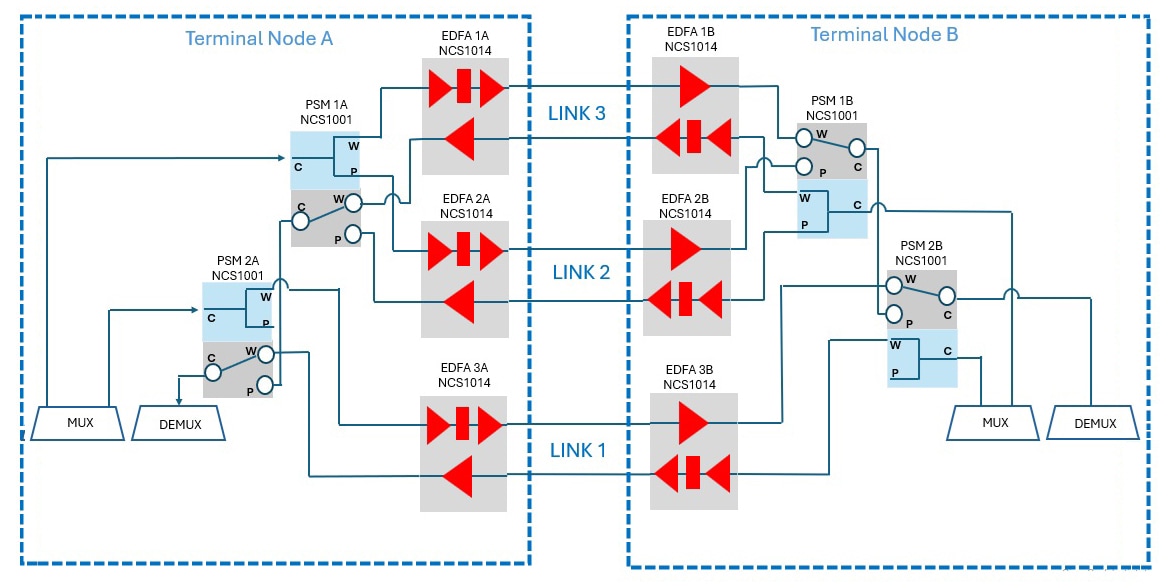
Figure 1. Three-way path protection setup with NCS1001 PSM and NCS1014 EDFA2

Limitations and requirements for three-way path protection

Use this reference to plan a three-way path protection deployment and to confirm the supported behavior of the cascaded NCS1001 PSMs with the NCS1014 EDFA2 amplifier.

The three-way path protection scheme has these limitations:

  • Unpredictable link selection: Post-switch, the link selection behavior of cascaded PSMs can be unpredictable or random link will be selected.

  • Possible routing asymmetry: The routing of the channels across the cascaded PSMs may become asymmetrical between the two transmission directions after a fiber cut or a manual switch.

  • Bidirectional switching not guaranteed on link 3: After a manual PSM switch, bidirectional switching might not occur for link 3 because it is connected only on the transmission side of the protected ports

For more information on PSM limitations, see the Cisco NCS 1001 configuration guide.

Software and hardware requirements

Table 2. Software and hardware requirements

Component

Minimum software release

Role

NCS1001 with NCS1K-PSM

Cisco IOS XR Release 25.4.1

Provides the cascaded protection switching modules at the receiving end of each terminal node.

NCS1014 with EDFA2

Cisco IOS XR Release 26.2.1

Provides the EDFA2 amplifiers on each of the three optical links between the two terminal nodes.

Service disruption

All service disruption times that are measured on the client interfaces of the transponders, configured at 400G, after a fiber cut or a manual switch, are below 50 ms.


Configure NCS1014 EDFA2 amplifiers for three-way path protection

Use this procedure to ensure each EDFA2 amplifier operates within a three-way path protection scheme, enabling stable optical communication and equalized signal levels.

Configure the EDFA2 amplifier on each of the three optical links between the two terminal nodes. The configuration uses the existing NCS1014 EDFA2 platform functionality from Cisco IOS XR Release 26.2.1.

Before you begin

  • Install the EDFA2 card in the target slot of the NCS1014 chassis.

  • Confirm that the NCS1014 runs Cisco IOS XR Release 26.2.1 or later.

  • Plan the IP addressing scheme for the OSC interface on each EDFA2 amplifier.

Procedure

1.

Configure the IPv4 address on the GigabitEthernet OSC interface in the global configuration mode.

Example:

RP/0/RP0/CPU0:ios# configure
RP/0/RP0/CPU0:ios(config)# interface GigabitEthernet0/1/0/5
RP/0/RP0/CPU0:ios(config-if)# ipv4 address 10.0.0.1 255.255.252.0
RP/0/RP0/CPU0:ios(config-if)# exit
2.

Enable OSPF on the OSC interface to establish a connection between the near-end EDFA and its corresponding far-end EDFA.

Example:

RP/0/RP0/CPU0:ios(config)# router ospf 1
RP/0/RP0/CPU0:ios(config-ospf)# distribute link-state
RP/0/RP0/CPU0:ios(config-ospf)# network point-to-point
RP/0/RP0/CPU0:ios(config-ospf)# area 0
RP/0/RP0/CPU0:ios(config-ospf-ar)# interface GigabitEthernet0/1/0/5
RP/0/RP0/CPU0:ios(config-ospf-ar-if)# exit
3.

Enable span-mode automatic power control on the OSC controller.

Example:

RP/0/RP0/CPU0:ios(config)# optical-line-control controller Osc0/1/0/0
RP/0/RP0/CPU0:ios(config-olc-osc)# osc-regulation span-mode
RP/0/RP0/CPU0:ios(config-olc-osc)# exit
4.

Enable amplifier APC in span mode and channel APC with flat power spectral density (PSD) equalization mode on the input OTS controller.

Example:

RP/0/RP0/CPU0:ios(config)#optical-line-control
RP/0/RP0/CPU0:ios(config-olc)# controller Ots0/1/0/0
RP/0/RP0/CPU0:ios(config-olc-ots)# ampli-apc span-mode
RP/0/RP0/CPU0:ios(config-olc-ots)# channel-apc
RP/0/RP0/CPU0:ios(config-olc-ots)# flat-psd-eq-mode
RP/0/RP0/CPU0:ios(config-olc-ots)# psd-target -190
RP/0/RP0/CPU0:ios(config-olc-ots)# exit

The psd-target value is in tenths of a dBm/GHz. The value -190 sets a -19.0 dBm/GHz target.

5.

Enable amplifier APC in span mode on the output OTS controller.

Example:

RP/0/RP0/CPU0:ios(config)#optical-line-control
RP/0/RP0/CPU0:ios(config-olc)# controller Ots0/1/0/1
RP/0/RP0/CPU0:ios(config-olc-ots)# ampli-apc span-mode
RP/0/RP0/CPU0:ios(config-olc-ots)# exit
6.

Commit the configuration.

Example:

RP/0/RP0/CPU0:ios(config)# commit

Each EDFA2 amplifier establishes OSPF adjacency with its far-end counterpart over the OSC interface. Span-mode APC stabilizes the optical signal, and channel APC equalizes power spectral density at the channel level. The amplifier is now ready to participate in the three-way path protection scheme with the NCS1001 PSM.


Configure the NCS1001 PSM for three-way path protection

Use this task to enable resilient service for 400G client interfaces by configuring the PSM to switch paths quickly after a fiber cut or manual switch.

This task sets the PSM on each NCS1001 chassis to work with the NCS1014 EDFA2 amplifier for three-way path protection. Thresholds are set so service disruption remains below 50 ms. You can configure thresholds manually or enable auto-threshold with a 3 dB offset.

Before you begin

Procedure

1.

Set the primary path of the PSM to the working port and enable the auto-threshold feature with a 3 dB offset.

Example:

RP/0/RP0/CPU0:ios(config)# hw-module location 0/RP0/CPU0 slot 1 psm primary-path WORKING
RP/0/RP0/CPU0:ios(config)# hw-module location 0/RP0/CPU0 slot 1 psm auto-threshold auto-threshold-offset 30

The auto-threshold-offset value is in tenths of a dB. The value 30 sets a 3 dB offset, which is the default value.

2.

Set the receive low threshold on the OTS controller of the PSM port.

Example:

RP/0/RP0/CPU0:ios(config)# controller Ots0/1/0/0
RP/0/RP0/CPU0:ios(config-Ots)# rx-low-threshold -200

The rx-low-threshold value is in tenths of a dBm. The value -200 sets a -20.0 dBm receive low threshold.

3.

Commit the configuration.

Example:

RP/0/RP0/CPU0:ios(config-Ots)# commit
4.

Verify the running configuration of the PSM.

Example:

RP/0/RP0/CPU0:ios# show running-config hw-module location 0/RP0/CPU0 slot 1
hw-module location 0/RP0/CPU0 slot 1
 psm primary-path WORKING
 psm auto-threshold
!
controller Ots0/1/0/0
 rx-low-threshold -200
!

The PSM uses the working port as the primary path. The receive low threshold of the working and protected ports stays 3 dB below the Rx power value, which keeps service disruption on the 400G client interfaces below 50 ms after a fiber cut or a manual switch.