Configuration Guide for Cisco NCS 1014, IOS XR Releases 26.x.x

PDF

Configuration Guide for Cisco NCS 1014, IOS XR Releases 26.x.x

2.4T, 2.4TX, and 2.4TA card modes

Want to summarize with AI?

Log in

This section explains the characteristics and configuration modes for 2.4T, 2.4TX, and 2.4TA line cards, including trunk and client mappings, data rates, and muxponder modes.


This section helps you familiarize with the different card modes available in the 2.4T, 2.4TX, and 2.4TA cards , their corresponding data rates, baud rate of each data rate, and the step-by-step procedure to configure line card in muxponder modes with the QDD-4x100GE and QDD-400GE pluggables.

Table 1. Feature History

Feature Name

Release Information

Feature Description

Muxponder Slice and Muxponder card modes for NCS1K14-2.4T-A-K9 Line Card

Cisco IOS Release 26.1.1

The new NCS1K14-2.4T-A-K9 line card supports both Muxponder Slice and Muxponder card modes, similar to the 2.4T and 2.4TX transponder cards. It can handle 1.2T of data per trunk and supports client data rates of 100GE and 400GE, with the capability to increase up to 800G per client.

By grouping multiple client interfaces, muxponder slice and muxponder card modes enhances bandwidth utilization for efficient transport over high-capacity DWDM links.

Available card modes

The 2.4T, 2.4TX, and 2.4TA line cards have two trunk ports (0 and 7) and six client ports (from 1 to 6) each. You can configure the line card in:

  • Muxponder slice: You can configure each trunk port independent of the other with different trunk rates. The client-to-trunk mapping is fixed. For Trunk 0, the client ports are 1 to 3. For Trunk 7, the client ports are 4 to 6.

  • Muxponder: You can configure both trunk ports with the same trunk rate. The client-to-trunk mapping is fixed.

    Note

    The 2.4T card does not support muxponder mode.

2.4T, 2.4TX, and 2.4TA card trunk pluggables and datarates

Coherent Interconnect Module 8

The 2.4T, 2.4TX, and 2.4TA cards support Coherent Interconnect Module 8 (CIM8) pluggables as trunk pluggables.

The Coherent Interconnect Module 8 (CIM8) is a pluggable, high-capacity multi-haul transceiver. The module can operate at line rates between 400G and 1200G in 100G increments. It utilizes a single optical carrier for both C-band and L-band operations.

CIM8-C-K9

CIM8-C-K9 is the C-band Coherent Interconnect module 8.

The frequency range supported on a 50 GHz or 100 MHz flex grid is from 1912500 to 1961000. Any frequency outside this range will trigger a "Port Pluggable Module Mismatched With Pre-Provisioned PPM" alarm, causing the link to go down.

The default frequency is 193.10 THz.

CIM8-CE-K9

CIM8-CE-K9 includes a pre-amplifier (EDFA).

The frequency range supported on a 50 GHz or 100 MHz flex grid is from 1912500 to 1961000. Any frequency outside this range will trigger a "Port Pluggable Module Mismatched With Pre-Provisioned PPM" alarm, causing the link to go down.

Due to the inclusion of the pre-amplifier, the optical performance is enhanced compared to the CIM8-C-K9, enabling longer reach.

CIM8-LE-K9

This variant of the CIM8 supports the L-band spectrum and includes a pre-amplifier (EDFA).

The frequency range supported on a 100 MHz flex grid is from 1861500 to 1909250.Any frequency outside this range triggers a "Port Pluggable Module Mismatched With Pre-Provisioned PPM" alarm, causing the link to go down.

There is no default frequency for the CIM8-LE-K9. You must configure the frequency for the laser to be activated.

In Release 24.3.1 and later releases, if a C-band CIM8 is replaced with an LE CIM8 and the frequency is configured within the specified range, the traffic should resume seamlessly.

From Release 24.4.1, there is no default frequency for any CIM8 pluggables. You must configure the frequency for the laser to be activated.

If data path is configured and default frequency is not configured on a port, then Mandatory Configuration Missing alarm is raised on that optics port.

PID

Frequency range supported

CIM8-C-K9

1912500 to 1961000

CIM8-CE-K9

1912500 to 1961000

CIM8-LE-K9

1861500 to 1909250

This table shows the different pluggables and datarates that each pluggable supports.

PID

Cards supported

Supported rates
CIM8-C-K9 2.4T, 2.4TX, and 2.4TA 400G, 500G, 600G, 700G, 800G, 900G, 1000G, 1100G, 1200G
CIM8-CE-K9 2.4TX and 2.4TA 400G, 500G, 600G, 700G, 800G, 900G, 1000G, 1100G, 1200G
CIM8-LE-K9 2.4TX and 2.4TA 400G, 500G, 600G, 700G, 800G, 900G, 1000G

QPSK modulation in CIM8 pluggables for 400G trunk rate

QPSK modulation in CIM8 pluggables refers to a line-side signal configuration.

Until Release 25.2.1, the CIM8 pluggable supported only the PCS-based modulation format for line-side configurations. This format was enabled by default and could not be changed by the user. For a 400G trunk rate, the default setting is 128 GBd with PCS modulation.

From Release 25.3.1, CIM8 pluggables on the NCS1K4-2.4T-K9, NCS1K14-2.4T-X-K9, NCS1K14-2.4TXL-K9 and NCS1K14-2.4T-L-K9 cards support 400G QPSK modulation. When the user configures the baud rate to 118 GBd for a trunk rate of 400G, the system automatically selects QPSK modulation.

Table 2. Feature History

Feature Name

Release Information

Description

QPSK modulation support for 400G trunk rate

Cisco IOS XR Release 25.3.1

The NCS1K4-2.4T-K9, NCS1K14-2.4T-X-K9, NCS1K14-2.4TXL-K9, and NCS1K14-2.4T-L-K9 cards now support QPSK modulation configuration for 400G trunk rate on CIM8 pluggables at a baud rate of 118 GBd.

This enhancement delivers improved performance and extended reach for long-distance and subsea applications.


Verify QPSK modulation in CIM8 pluggables

You can confirm that QPSK modulation is correctly enabled and functioning on the CIM8 pluggables.

Procedure

Run the show controller controllertype R/S/I/P command to verify the QPSK modulation on the CIM8 pluggables for baud rate 118.

Example:


RP/0/RP0/CPU0:NE2063#show controllers optics 0/2/0/0 
Wed Aug 13 08:59:58.896 UTC
 Controller State: Up 
 Transport Admin State: In Service 
 Laser State: On 
 LED State: Green 
 Last link flapped: 00:13:23
 
 Optics Status 
         Optics Type:  CIM8 DWDM
         DWDM carrier Info: C BAND, MSA ITU Channel=1, Frequency=196.10THz,
         Wavelength=1528.773nm 

         Alarm Status:
         -------------
         Detected Alarms: None
         LOS/LOL/Fault Status:
         Alarm Statistics:
         -------------
         HIGH-RX-PWR = 0            LOW-RX-PWR = 2          
         HIGH-TX-PWR = 0            LOW-TX-PWR = 1          
         HIGH-LBC = 0               HIGH-DGD = 0          
         OOR-CD = 0                 OSNR = 3          
         WVL-OOL = 0                MEA  = 0          
         IMPROPER-REM = 0          
         TX-POWER-PROV-MISMATCH = 0          
         Laser Bias Current = 0.0 %
         Actual TX Power = 2.01 dBm 
         RX Power = 1.28 dBm 
         RX Signal Power = 1.35 dBm 
         Frequency Offset = -61 MHz 

         Performance Monitoring: Enable 

         THRESHOLD VALUES
         ----------------
         Parameter                 High Alarm  Low Alarm  High Warning  Low Warning
         ------------------------  ----------  ---------  ------------  -----------
         Rx Power Threshold(dBm)         13.0      -25.0           0.0          0.0
         Tx Power Threshold(dBm)          5.0      -13.0           0.0          0.0
         LBC Threshold(mA)                N/A        N/A          0.00         0.00

         LBC High Threshold = 90 % 
         Configured Tx Power = 2.00 dBm 
         Configured CD High Threshold = 600000 ps/nm 
         Configured CD lower Threshold = -600000 ps/nm 
         Configured OSNR lower Threshold = 14.50 dB 
         Configured DGD Higher Threshold = 103.00 ps 
         Baud Rate =  118.7111970000 GBd
         Bits per Symbol = 2.0000000000  bits/symbol 
         Modulation Type: QPSK 
         Chromatic Dispersion -1 ps/nm 
         Configured CD-MIN -10000 ps/nm  CD-MAX 90000 ps/nm 
         Polarization Mode Dispersion = 0.0 ps 
         Second Order Polarization Mode Dispersion = 40.00 ps^2 
         Optical Signal to Noise Ratio = 40.00 dB 
         SNR = 19.30 dB 
         Polarization Dependent Loss = 1.40 dB 
         Polarization Change Rate = 0.00 rad/s 
         Differential Group Delay = 2.00 ps 
         Filter Roll Off Factor : 0.100 
         Rx VOA Gain Offset : 0.00 dB
         NLEQ Compensation Mode : 0
         Cross Polarization Gain Mode : 10
         Proprietary Submarine Parameters
           Type : 1        Value : 0
           Type : 2        Value : 0
           Type : 3        Value : 0
           Type : 4        Value : 0
           Type : 5        Value : 10485760
           Type : 6        Value : 0
 Transceiver Vendor Details
         Form Factor            : CIM8
         Name                   : CISCO-ACACIA    
         Part Number            : 10-100471-02
         Rev Number             : A0 
         Serial Number          : ACA29160037
         PID                    : CIM8-C-K9
         VID                    : V02
         Firmware Version       : Major.Minor.Build
         Active                 : 80.140.8
         Inactive               : 80.130.21
         Date Code(yy/mm/dd)    : 25/04/10
         Fiber Connector Type: LC 
         Otn Application Code: Not Set 
         Sonet Application Code: Not Set 
         Ethernet Compliance Code: Not set 
 Transceiver Temperature : 38 Celsius
 
 AINS Soak                : None 
 AINS Timer               : 0h, 0m
 AINS remaining time      : 0 seconds

RP/0/RP0/CPU0:NE2063# 

Muxponder slice mode for 2.4T, 2.4TX, and 2.4TA cards

This section details the slice and ports supported on the 2.4T, 2.4TX, and 2.4TA cards.

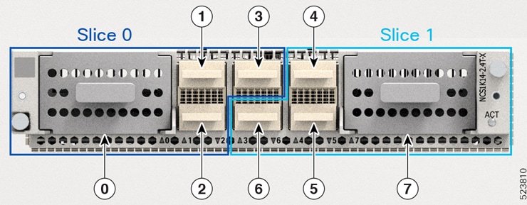
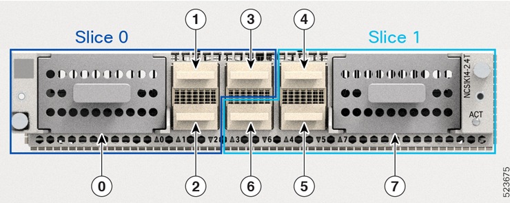
The line card is divided into two slices, namely, Slice 0 and Slice 1. Each slice contains a trunk port and three client ports. In this mode, the trunk ports operate independently, carrying different data rates. The slices enable the card to function as two different modules. For example, if you set the trunk as 400 G for Slice 0 and 600 G for Slice 1, then Trunk 0 delivers 400 G and Trunk 7 delivers 600 G.

Figure 1. 2.4T lne card slices and ports
2.4TX and 2.4TA
Figure 2. line card slices and ports
Table 3. Client-to-trunk mapping in slice 0 and slice 1 modes

Slice 0

Slice 1

Trunk port

Client ports

Trunk port

Client ports

0

1, 2, 3

7

4, 5, 6


Data rate capabilities for 2.4T, 2.4TX, and 2.4TA cards in muxponder slice mode

The 2.4T, 2.4TX, and 2.4TA line cards support various trunk rates.
This table shows the releases from which the 2.4T, 2.4TX, and 2.4TA cards started supporting each trunk rate.
Table 4. Release-wise trunk rates supported by the 2.4T, 2.4TX, and 2.4TA cards

Trunk rate (G)

2.4T

2.4TX

2.4TA

400

7.11.1

24.1.1

26.1.1

500

24.1.1

26.1.1

600

7.11.1

24.1.1

26.1.1

700

-

24.2.1

26.1.1

800

7.11.1

24.1.1

26.1.1

900

-

24.2.1

26.1.1

1000

7.11.1

24.1.1

26.1.1

1100

-

24.2.1

26.1.1

1200

-

24.1.1

26.1.1


This section details the baud rate range for each trunk rate in the 2.4T, 2.4TX, and 2.4TA cards.

Baud rate ranges for each trunk rate in the 2.4T, 2.4TX, and 2.4TA cards

The 2.4T, 2.4TX, and 2.4TA cards carries signals at different trunk rates, with each trunk rate operating within a baud rate range.

In the Baud Rate Ranges for Each Trunk Rate in the 2.4T, 2.4TX, and 2.4TAcards table, you can find the recommended baud rate ranges to maintain the signal health for each trunk rate in the network.

Baud rate and bit rate range for each trunk rate in the 2.4TX card

The 2.4TX card carries trunk signals at different data rates. Each trunk data rate operates in a default baud rate. However, you can customize the baud rate within the recommended baud rate range based on your deployment scenario. To customize baud rate, see.

In the Baud Rate and Bit Rate Range for Each Trunk Rate in the 2.4TX Card table, you can find the recommended baud rate ranges to maintain the signal health for each trunk rate in the network. The table also features the bit per second information for the respective baud rates.

Table 5. Baud rate and bit rate range for each trunk rate in the 2.4TX and 2.4TA card

Trunk data rate per trunk (G)

Minimum baud r ate (GBd)

Maximum baud rate (GBd)

Default baud rate (GBd)

Minimum bit per second (bps)

Maximum bit per second (bps)

400

62

128

127.931418

2.1

4.1

500

62

138

137.834059

2.5

5

600

72

138

137.738007

2.8

5.1

700

88

138

138.08166

3.2

5

800

98

138

137.978388

3.5

5.1

900

108

138

137.89817

3.8

5.2

1000

99.22392

138

137.834059

4.3

5.3

1100

118

138

137.78165

4.7

5.3

1200

128

138

137.738007

5.3

5.7


Customize baud rates

Customizing baud rates is to enable users to adjust the default baud rates for the 2.4T, 2.4TX, and 2.4TA cards, particularly when operating in muxponder mode. This customization allows for optimization of network bandwidth based on specific deployment scenarios and ensures that the baud rates align with the available bandwidth in the network.

The muxponder mode enables the 2.4T, 2.4TX, and 2.4TA cards to carry signals in default baud rates when you set up the trunk rate. However, you can customize the baud rates for each trunk rate based on the bandwidth in the network.

Use this task to customize the baud rates within the recommended range as per your deployment scenario.

Before you begin

  • Install these pluggable modules as required.

    • QDD-4x100G

    • QDD-400G

  • Enter the Cisco IOS XR configuration mode.

Procedure

1.

Locate the trunk optics controller for the 2.4T, 2.4TX, and 2.4TA cards.

Example:

RP/0/RP0/CPU0:ios(config)# controller optics 0/0/0/7
2.

Enter baud rate.

Example:

RP/0/RP0/CPU0:ios(config-Optics)# baud-rate 120.0000
3.

Save the changes.

Example:

RP/0/RP0/CPU0:ios(config-Optics)#commit

Client pluggables for configuring muxponder slice modes

This section provides details about the client pluggable combinations that you need to set up the client rate for each trunk rate in slice 0 and slice 1.

Pluggable combinations in muxponder slice modes

The client data rates and ports differ for each trunk rate in the muxponder slice 0 (Trunk 0) and muxponder slice 1 (Trunk 1) configurations. However, the type of client pluggable modules stays the same for both slice modes.

Note

The 2x 100 GE client rate is supported only on 2.TX cards.

Table 6. Trunk rate and client pluggable combinations for Slices 0 and Slice 1

Trunk rate (G) per trunk

Card support

Client rate

Client pluggable

Client ports

Slice 0

Slice 1

400

2.4T, 2.4TX, 2.4TA

2x 100 GE

400 GE

QDD-400G 1

1

4

2x 100 GE

4x 100 GE

QDD-4x100G2

500

2.4T, 2.4TX

, 2.4TA

2x 100 GE

400 GE + 1x 100 GE

QDD-400G 1+ QDD-4x100G2

1, 2

4, 5

5x 100 GE

2x QDD-4x100G2

600

2.4T, 2.4TX, 2.4TA

400 GE + 2x 100 GE

QDD-400G 1 + QDD-4x100G2

1, 2

4, 5

6x 100 GE

2x QDD-4x100G2

700

2.4T, 2.4TX

, 2.4TA

2x 100 GE

400 GE + 3x 100 GE

QDD-400G 1 + QDD-4x100G2

1, 2

4, 5

7x 100 GE

2x QDD-4x100G2

800

2.4T, 2.4TX, 2.4TA

2x 100 GE

2x 400 GE

2x QDD-400G 1

1, 2

4, 5

400 GE + 4x 100 GE

QDD-400G 1 + QDD-4x100G2

8x 100 GE

2x QDD-4x100G2

900

2.4T, 2.4TX

, 2.4TA

2x 100 GE

2x 400 GE + 1x 100 GE

QDD-400G 1 + QDD-4x100G2

1, 2, 3

4, 5, 6

400 GE + 5x 100 GE

QDD-400G 3 + QDD-4x100G4

9x 100 GE 3x QDD-4x100G2

1000

2.4T, 2.4TX, 2.4TA

2x 100 GE

2x 400GE + 2x 100 GE

2x QDD-400G 1 + 2x QDD-4x100G2

1, 2, 3

4, 5, 6

10x 100 GE

3x QDD-4x100G2

1100

2.4TX

, 2.4TA

2x 100 GE

2x 400 GE + 3x 100 GE

2x QDD-400G 1 + QDD-4x100G2

1, 2, 3

4, 5, 6

400 GE + 7x 100 GE

2x QDD-400G 1 + QDD-4x100G2

11x 100 GE

3x QDD-4x100G2

1200

2.4TX

3x 400 GE

3x QDD-400G 1

1, 2, 3

4, 5,6

2x 400 GE + 4x 100 GE

2x QDD-400G 1 + QDD-4x100G2

400 GE + 8x 100 GE

QDD-400G 1 + 2x QDD-4x100G2

12x 100 GE

3x QDD-4x100G2

6x 2X100 GE

6x QDD-2X100-CWDM4-S

1, 2, 3, 4, 5, 6

6x QDD-2X100-LR4-S

1 QDD-400G refers to QDD-400G-FR4-S, QDD-400G-LR4-S, QDD-400G-AOCxM, and QDD-400G-DR4-S pluggable modules.
2 QDD-4x100G refers to QDD-4X100G-LR-S, QDD-4X100G-FR-S, and QDD-400G-DR4-S pluggable modules.

Make sure you use the appropriate values for client bitrate and trunk bitrate parameters when configuring the Muxponder slide mode using the hw-module command.


Set up the client and trunk rate in the muxponder slice mode for 2.4T, 2.4TX, and 2.4TA cards

Set up the client and trunk rate in the muxponder slice mode for the 2.4T, 2.4TX, and 2.4TA cards to configure these cards to handle specific data rates for both the aggregated trunk and individual client ports.

Use this task to set up the client and trunk rate in the muxponder slice mode for the 2.4T, 2.4TX, and 2.4TA cards.

This task considers that you are setting up the 600-G data rate in one of the trunk ports of the 2.4T, 2.4TX, and 2.4TA cards. This scenario requires you to set the client rate for the client ports. Based on the client pluggable that you use, the client rate can change to 400-GE client, 100-GE client, or mixed client.

For more information on the the data rate on each client port, see Client pluggables for configuring muxponder slice modes .

Before you begin

  • Install these pluggables as required.

    • QDD-400G

    • QDD-4x100G

Procedure

1.

Specify the card location.

Example:

RP/0/RP0/CPU0:ios(config)#hw-module location 0/1/NXR0
2.

Configure the 2.4T or 2.4TX or 2.4TA line card in the muxponder slice mode.

For Trunk 0 port, enter the muxponder-slice 0 mode.

Example:

RP/0/RP0/CPU0:ios(config)# mxponder-slice 0

For Trunk 1 port, enter the muxponder-slice 1 mode.

Example:

RP/0/RP0/CPU0:ios(config)# mxponder-slice 1
Note

You can configure both muxponder slice 0 and slice 1 modes when needed.

For more information on how to configure muxponder slice mode with QDD-4x100GE and QDD-4x100GE pluggables, see the hw-module command.

3.

Set up the trunk rate for the 2.4T or 2.4TX or 2.4TA card.

Example:

RP/0/RP0/CPU0:ios(config-hwmod-mxp)#trunk-rate 600G
4.

Set up the client rate based on the pluggables that you use.

For the QDD-400G pluggable, run this command.

Example:


RP/0/RP0/CPU0:ios(config-hwmod-mxp)#
client-port-rate 1 client-type 400GE
RP/0/RP0/CPU0:ios(config-hwmod-mxp)#
client-port-rate 2 client-type 400GE

For the QDD-4x100G pluggable, run this command.

Example:


RP/0/RP0/CPU0:ios(config-hwmod-mxp)#
client-port-rate 1 lane 1 client-type 100GE
RP/0/RP0/CPU0:ios(config-hwmod-mxp)#
client-port-rate 1 lane 2 client-type 100GE
RP/0/RP0/CPU0:ios(config-hwmod-mxp)#
client-port-rate 1 lane 3 client-type 100GE
RP/0/RP0/CPU0:ios(config-hwmod-mxp)#
client-port-rate 1 lane 4 client-type 100GE
RP/0/RP0/CPU0:ios(config-hwmod-mxp)#
client-port-rate 2 lane 1 client-type 100GE
RP/0/RP0/CPU0:ios(config-hwmod-mxp)#
client-port-rate 2 lane 2 client-type 100GE
Note

Use the lane keyword to set up the 100-GE client rate in the client ports.

For the mixed client pluggable, use the combination of the QDD-400G and QDD-4x100G commands.

5.

Save the configuration and exit the muxponder slice mode.

Example:

Command

RP/0/RP0/CPU0:ios(config-hwmod-mxp)#
commit
RP/0/RP0/CPU0:ios(config-hwmod-mxp)#
exit
RP/0/RP0/CPU0:ios(config)#
exit
6.

Verify the 600-G data rate that you set up.

This sample shows the 600-G data rate ( Trunk Bitrate: 600G ) set up in client ports 1 ( FourHundredGigECtrlr0/1/0/1 ) and 2 with breakout lanes 1 and 2 ( HundredGigECtrlr0/1/0/2/1 and HundredGigECtrlr0/1/0/2/2 ) using 400-GE and 100-GE client type pluggables ( Client Bitrate: MIXED ) in muxponder slice 0 ( Slice ID: 0 ).

Example:


RP/0/RP0/CPU0:ios#show hw-module location 0/1/NXR0 mxponder-slice 0
Thu Nov 16 15:41:25.720 UTC
Location:             0/1/NXR0
Slice ID: 0 Client Bitrate: MIXED Trunk Bitrate: 600G
Status:               Provisioned
LLDP Drop Enabled:    FALSE
ARP Snoop Enabled:    FALSE
Client Port                     Mapper/Trunk Port          CoherentDSP0/1/0/0
Traffic Split Percentage
FourHundredGigECtrlr0/1/0/1 ODU-FLEX0/1/0/0/1 100 
   HundredGigECtrlr0/1/0/2/1 ODU-FLEX0/1/0/0/2/1 100 
   HundredGigECtrlr0/1/0/2/2 ODU-FLEX0/1/0/0/2/2 100

This sample shows the 600-G data rate ( Trunk Bitrate: 600G ) set up in client ports 0 with breakout lanes 1 to 4 ( HundredGigECtrlr0/1/0/1/1 to HundredGigECtrlr0/1/0/1/4 ) and 1 ( HundredGigECtrlr0/1/0/2/1 ) using 100-GE client type pluggable ( Client Bitrate: 100GE ) in muxponder slice 0 ( Slice ID: 0 ).

Example:


RP/0/RP0/CPU0:ios#show hw-module location 0/1/NXR0 mxponder-slice 0
Thu Nov 16 16:06:57.575 UTC
Location:             0/1/NXR0
Slice ID: 0 Client Bitrate: 100GE Trunk Bitrate: 600G
Status:               Provisioned
LLDP Drop Enabled:    FALSE
ARP Snoop Enabled:    FALSE
Client Port           Mapper/Trunk Port          CoherentDSP0/1/0/0
Traffic Split Percentage
HundredGigECtrlr0/1/0/1/1 ODU-FLEX0/1/0/0/1/1 100 
   HundredGigECtrlr0/1/0/1/2 ODU-FLEX0/1/0/0/1/2 100 
   HundredGigECtrlr0/1/0/1/3 ODU-FLEX0/1/0/0/1/3 100 
   HundredGigECtrlr0/1/0/1/4 ODU-FLEX0/1/0/0/1/4 100 
   HundredGigECtrlr0/1/0/2/1 ODU-FLEX0/1/0/0/2/1 100 
   HundredGigECtrlr0/1/0/2/2 ODU-FLEX0/1/0/0/2/2 100

Set up 2x100G clients in 800G to 1200G trunk rates in the muxponder slice mode for 2.4TX card

Use this task to set up 2x100G client pluggables in 800G to 1200G trunk rates in the muxponder slice mode for the 2.4TX card.

For more information on the data rate on each client port, see Client pluggables for configuring muxponder slice modes.

Before you begin

  • Install either of these pluggables in all 6 client ports.

    • QDD-2X100-CWDM4-S

    • QDD-2X100-LR4-S

Procedure

1.

Specify the card location.

Example:

RP/0/RP0/CPU0:ios(config)#hw-module location 0/1/NXR0
2.

Configure the 2.4TX and 2.4TA line cards in the muxponder slice mode.

For 6x2x100pluggables in 800G to 1200G trunk modes all client ports are in slice 0. Enter the muxponder-slice 0 mode.

Example:

RP/0/RP0/CPU0:ios(config)#mxponder-slice 0
3.

Set up the trunk rate for the 2.4TX and 2.4TA cards.

These examples show how to set up various trunk rates in the muxponder slice mode.

Example:

RP/0/RP0/CPU0:ios(config-hwmod-mxp)#trunk-rate 1200G

Example:

RP/0/RP0/CPU0:ios(config-hwmod-mxp)#trunk-rate 1100G

Example:

RP/0/RP0/CPU0:ios(config-hwmod-mxp)#trunk-rate 1000G

Example:

RP/0/RP0/CPU0:ios(config-hwmod-mxp)#trunk-rate 900G

Example:

RP/0/RP0/CPU0:ios(config-hwmod-mxp)#trunk-rate 800G
4.

Set up the client rate.

For the 2X100G pluggables, run this command.

Example:

RP/0/RP0/CPU0:ios(config-hwmod-mxp)#client-rate 100GE 
5.

Save the configuration and exit the muxponder slice mode.

Example:

Command

RP/0/RP0/CPU0:ios(config-hwmod-mxp)#commit
RP/0/RP0/CPU0:ios(config-hwmod-mxp)#exit
RP/0/RP0/CPU0:ios(config)#exit
6.

Verify the data rate that you set up.

This sample shows the 800G data rate set up in the client ports 1, 2, 4, and 5.

Example:


RP/0/RP0/CPU0:ios#show hw-module location 0/1/NXR0 mxponder-slice 0                     
Mon Aug 18 02:11:25.625 UTC

Location:             0/1/NXR0
Slice ID:             0
Client Bitrate:       100GE
Trunk  Bitrate:       800G
Status:               Provisioned
LLDP Drop Enabled:    FALSE
ARP Snoop Enabled:    FALSE
Client Port                     Mapper/Trunk Port          CoherentDSP0/1/0/0   
                                Traffic Split Percentage

HundredGigECtrlr0/1/0/1/1       ODU-FLEX0/1/0/0/1                             100
HundredGigECtrlr0/1/0/1/5       ODU-FLEX0/1/0/0/2                             100
HundredGigECtrlr0/1/0/2/1       ODU-FLEX0/1/0/0/3                             100
HundredGigECtrlr0/1/0/2/5       ODU-FLEX0/1/0/0/4                             100
HundredGigECtrlr0/1/0/4/1       ODU-FLEX0/1/0/0/5                             100
HundredGigECtrlr0/1/0/4/5       ODU-FLEX0/1/0/0/6                             100
HundredGigECtrlr0/1/0/5/1       ODU-FLEX0/1/0/0/7                             100
HundredGigECtrlr0/1/0/5/5       ODU-FLEX0/1/0/0/8                             100

This sample shows the 900G data rate set up in the client ports 1, 2, 3, 4, and 5.

Example:


RP/0/RP0/CPU0:ios#show hw-module location 0/1 mxponder-slice 0
Mon Aug 18 02:15:28.412 UTC

Location:             0/1/NXR0
Slice ID:             0
Client Bitrate:       100GE
Trunk  Bitrate:       900G
Status:               Provisioned
LLDP Drop Enabled:    FALSE
ARP Snoop Enabled:    FALSE
Client Port                     Mapper/Trunk Port          CoherentDSP0/1/0/0   
                                Traffic Split Percentage

HundredGigECtrlr0/1/0/1/1       ODU-FLEX0/1/0/0/1                             100
HundredGigECtrlr0/1/0/1/5       ODU-FLEX0/1/0/0/2                             100
HundredGigECtrlr0/1/0/2/1       ODU-FLEX0/1/0/0/3                             100
HundredGigECtrlr0/1/0/2/5       ODU-FLEX0/1/0/0/4                             100
HundredGigECtrlr0/1/0/3/1       ODU-FLEX0/1/0/0/5                             100
HundredGigECtrlr0/1/0/4/1       ODU-FLEX0/1/0/0/6                             100
HundredGigECtrlr0/1/0/4/5       ODU-FLEX0/1/0/0/7                             100
HundredGigECtrlr0/1/0/5/1       ODU-FLEX0/1/0/0/8                             100
HundredGigECtrlr0/1/0/5/5       ODU-FLEX0/1/0/0/9                             100

This sample shows the 1000G data rate set up in up in the client ports 1, 2, 3, 4, and 5.

Example:


RP/0/RP0/CPU0:ios#show hw-module location 0/1 mxponder-slice 0
Mon Aug 18 02:15:48.811 UTC

Location:             0/1/NXR0
Slice ID:             0
Client Bitrate:       100GE
Trunk  Bitrate:       1000G
Status:               Provisioned
LLDP Drop Enabled:    FALSE
ARP Snoop Enabled:    FALSE
Client Port                     Mapper/Trunk Port          CoherentDSP0/1/0/0   
                                Traffic Split Percentage

HundredGigECtrlr0/1/0/1/1       ODU-FLEX0/1/0/0/1                             100
HundredGigECtrlr0/1/0/1/5       ODU-FLEX0/1/0/0/2                             100
HundredGigECtrlr0/1/0/2/1       ODU-FLEX0/1/0/0/3                             100
HundredGigECtrlr0/1/0/2/5       ODU-FLEX0/1/0/0/4                             100
HundredGigECtrlr0/1/0/3/1       ODU-FLEX0/1/0/0/5                             100
HundredGigECtrlr0/1/0/3/5       ODU-FLEX0/1/0/0/6                             100
HundredGigECtrlr0/1/0/4/1       ODU-FLEX0/1/0/0/7                             100
HundredGigECtrlr0/1/0/4/5       ODU-FLEX0/1/0/0/8                             100
HundredGigECtrlr0/1/0/5/1       ODU-FLEX0/1/0/0/9                             100
HundredGigECtrlr0/1/0/5/5       ODU-FLEX0/1/0/0/10                            100

This sample shows the 1100G data rate set up in 1, 2, 3, 4, 5, and 6 client ports.

Example:


RP/0/RP0/CPU0:ios#show hw-module location 0/1/NXR0 mxponder-slice 0
Mon Aug 18 02:12:03.291 UTC

Location:             0/1/NXR0
Slice ID:             0
Client Bitrate:       100GE
Trunk  Bitrate:       1100G
Status:               Provisioned
LLDP Drop Enabled:    FALSE
ARP Snoop Enabled:    FALSE
Client Port                     Mapper/Trunk Port          CoherentDSP0/1/0/0   
                                Traffic Split Percentage

HundredGigECtrlr0/1/0/1/1       ODU-FLEX0/1/0/0/1                             100
HundredGigECtrlr0/1/0/1/5       ODU-FLEX0/1/0/0/2                             100
HundredGigECtrlr0/1/0/2/1       ODU-FLEX0/1/0/0/3                             100
HundredGigECtrlr0/1/0/2/5       ODU-FLEX0/1/0/0/4                             100
HundredGigECtrlr0/1/0/3/1       ODU-FLEX0/1/0/0/5                             100
HundredGigECtrlr0/1/0/3/5       ODU-FLEX0/1/0/0/6                             100
HundredGigECtrlr0/1/0/4/1       ODU-FLEX0/1/0/0/7                             100
HundredGigECtrlr0/1/0/4/5       ODU-FLEX0/1/0/0/8                             100
HundredGigECtrlr0/1/0/5/1       ODU-FLEX0/1/0/0/9                             100
HundredGigECtrlr0/1/0/5/5       ODU-FLEX0/1/0/0/10                            100
HundredGigECtrlr0/1/0/6/1       ODU-FLEX0/1/0/0/11                            100

This sample shows the 1200G data rate set up in all 12 client ports.

Example:


RP/0/RP0/CPU0:ios#show hw-module location 0/2/NXR0 mxponder-slice 0
Thu Nov 16 15:41:25.720 UTC
Location:             0/2/NXR0
Slice ID:             0
Client Bit100GE
Trunk  Bitrate:       1200G
Status:               Provisioned
rate:       LLDP Drop Enabled:    FALSE
ARP Snoop Enabled:    FALSE
Client Port                     Mapper/Trunk Port          CoherentDSP0/2/0/0   
                                Traffic Split Percentage

HundredGigECtrlr0/2/0/1/1       ODU-FLEX0/2/0/0/1                             100
HundredGigECtrlr0/2/0/1/5       ODU-FLEX0/2/0/0/2                             100
HundredGigECtrlr0/2/0/2/1       ODU-FLEX0/2/0/0/3                             100
HundredGigECtrlr0/2/0/2/5       ODU-FLEX0/2/0/0/4                             100
HundredGigECtrlr0/2/0/3/1       ODU-FLEX0/2/0/0/5                             100
HundredGigECtrlr0/2/0/3/5       ODU-FLEX0/2/0/0/6                             100
HundredGigECtrlr0/2/0/4/1       ODU-FLEX0/2/0/0/7                             100
HundredGigECtrlr0/2/0/4/5       ODU-FLEX0/2/0/0/8                             100
HundredGigECtrlr0/2/0/5/1       ODU-FLEX0/2/0/0/9                             100
HundredGigECtrlr0/2/0/5/5       ODU-FLEX0/2/0/0/10                            100
HundredGigECtrlr0/2/0/6/1       ODU-FLEX0/2/0/0/11                             100
HundredGigECtrlr0/2/0/6/5       ODU-FLEX0/2/0/0/12                            100

800GE client support for muxponder slice mode on 2.4T, 2.4TX, and 2.4TA cards

Supported client features

A 800GE client configuration is an Ethernet client-rate setup for 2.4T, 2.4TX, and 2.4TA line cards that:

  • enables port 2 and port 5 to carry 800 Gbps Ethernet traffic mapped to an 800G and higher trunk rate

  • applies to the NCS1K14-2.4T-K9 , NCS1K14-2.4T-X-K9 , and NCS1K14-2.4T-A-K9 line cards, and

  • uses the QDD-8X100-FR client pluggable with configuration controlled by trunk-rate and client-port-rate commands.

Table 7. Feature history

Feature name

Release information

Feature description

800GE Ethernet Support

Cisco IOS XR Release 26.2.1

The NCS1K14-2.4T-K9, NCS1K14-2.4T-X-K9, and NCS1K14-2.4T-A-K9 line cards now support the 800GE client rate mapped to an 800G trunk rate on port 2 and port 5 in muxponder slice mode.

New pluggable introduced:

QDD-8X100-FR

This provides support for the newer generation of high-capacity Ethernet client interfaces alongside 400GE and 100GE, enabling truly scalable and simplified deployments in both new (greenfield) and existing (brownfield) network environments.

These features are available for the 800GE client rate:

  • Laser Squelch

  • Loopback

  • Link Layer Discovery Protocol (LLDP)

  • Licensing

  • Automatic-In-Service (AINS)

  • Idle frame insertion

Table 8. Trunk rate and client rate combinations with 800GE client rate
Trunk rate (Port 0 or Port 7)​

Client rate (Port 1 or Port 4)​

Client rate (Port 2 or Port 5)​

Client rate (Port 3 or Port 6)​

800G

NA

800GE

NA

900G

NA

800GE 100GE
1000G

NA

800GE 100GE
1100G

NA

800GE 100GE
1200G

NA

800GE 400GE, 100GE
Note

Traffic compliance standards differ by platform. The 2.4T and 2.4TX platforms support 800GE ETC (Ethernet Technology Consortium), whereas the 2.4TA platform utilizes 800GE IEEE.


Configure the 800GE client rate in the muxponder slice mode

Set up an 800GE client port and an 800G trunk port within a muxponder slice.

Before you begin

The 800GE client rate requires the QDD-8X100-FR client pluggable. Install the pluggable in the client port you plan to configure for client-type 800GE before starting configuration.
Follow these steps to configure 800GE client rate in muxponder slice mode.

Procedure

1.

Run the configure hw-module location location mxponder-slice mxponder-slice-number trunk-rate 800G client-port-rate client-port-number client-type 800GE command to configure the line card in the muxponder slice mode.

Example:


RP/0/RP0/CPU0:ios#configure​
RP/0/RP0/CPU0:ios(config)# hw-module location 0/1/NXR0 mxponder-slice 0​
RP/0/RP0/CPU0:ios(config-hwmod-mxp)#trunk-rate 800G ​
RP/0/RP0/CPU0:ios(config-hwmod-mxp)#client-port-rate 2 client-type 800GE ​
RP/0/RP0/CPU0:ios(config-hwmod-mxp)#commit ​
RP/0/RP0/CPU0:ios#
2.

Run the Commit command to apply the changes.

3.

Run the show hw-module location mxponder-slice command to verify the 800GE client rate and the 800G trunk rate configuration.

Example:


RP/0/RP0/CPU0:ios#show hw-module location 0/1/NXR0 mxponder-slice 0
Location:             0/1/NXR0
Slice ID:             0
Client Bitrate:       800GE
Trunk Bitrate:        800G
Status:               Provisioned
LLDP Drop Enabled:    FALSE
ARP Snoop Enabled:    FALSE
Client Port                       Mapper/Trunk Port           CoherentDSP0/1/0/0
Traffic Split Percentage
EightHundredGigECtrlr0/1/0/2      ODU-FLEX0/1/0/0/2                          100

The line card runs the configured client port at 800GE, paired with the 800G trunk rate, in the selected muxponder slice.


Muxponder mode for 2.4TX and 2.4TA

The muxponder mode enables the 2.4TX and 2.4TA cards to split wavelengths in specific client ports between the two trunk ports. In the slice mode, the client ports that support wavelength splitting act the same as other client ports. However, in the muxponder mode, the 2.4TX and 2.4TA cards activates the split client ports. The shared client ports are client port 2 for 600G and client port 3 for 1000G.

How muxponder mode splits 400GE and 4x100GE client traffic

This use case explains the wavelength splitting for 600G trunk rate.

For 600G trunk rate, you must configure client port 1, 2, and 4 as 400GE or 4x100GE. Trunk 0 receives 400GE from port 1. Trunk 7 receives 400GE from port 4. As per split client configuration, port 2 gives 200GE to Trunk 0 and another 200GE to Trunk 7. In this way, both trunk ports deliver 600G trunk rate each.


  • Connect the port 0 and port 7 in the near end node to their respective port 0 and port 7 in the far end node.

  • Make sure the optic fibers connected to trunk ports 0 and 7 are the same length. The difference must be less than 500 m; otherwise, you'll lose traffic on the split port.


Data rate capabilities for the 2.4TX and 2.4TA card

Table 9. Feature History

Feature Name

Release Information

Description

Additional Muxponder Mode Trunk Rates for the NCS1K14-2.4T-X-K9 Line Card

Cisco IOS XR Release 24.3.1

The NCS1K14-2.4T-X-K9 line card now supports additional trunk rates of 500G and 900G in muxponder mode, enhancing flexibility and optimizing pluggable count alongside the existing 600G and 1000G rates.

To outline the data rate capabilities of the 2.4TX and 2.4TA card.

The 2.4TX and 2.4TA card supports different trunk rates.

Table 10. Release-wise trunk rates supported by the 2.4TX and 2.4TA cards

Trunk rate (G)

Release introduced

500

24.3.1

600

24.1.1

900G

24.3.1

1000G

24.1.1

800G

26.2.1

Note

For 600G and 1000G trunk rates, in R24.1.1, the shared client port supports only 400GE client and from R24.3.1, the shared client port supports both 400GE and 4x100GE clients.


Client pluggables for configuring 2.4TX and 2.4TA muxponder mode

Table 11. Feature History

Feature Name

Release Information

Description

100GE Channel Support for the 600G and 1000G Trunk Rate in NCS1K14-2.4T-X-K9 Muxponder Mode

Cisco IOS XR Release 24.3.1

The NCS1K14-2.4T-X-K9 line card now allows 100G breakout client support for 600G and 1000G trunk rate in muxponder mode. It features 4x100GE breakout channels in shared client ports, enabling easy integration with existing 100G networks using QDD-4X100G-LR-S, QDD-4X100G-FR-S, and QDD-400G-DR4-S pluggable modules. These channels offer high density and bandwidth efficiency without extra costs.

This section provides details about the client pluggable combinations that you need to set up the client rate for each trunk rate.

Client pluggable combinations in muxponder mode

The 2.4TX and 2.4TA muxponder mode supports various trunk rate per trunk with different client pluggable combinations.

Note

From R24.3.1, the 2.4TX card supports 100GE client traffic in the shared client port for both 600G and 1000G trunk rates.

Note

The 2.4TA card does not support 2x100GE.

The client channel rate in the table refers to both the total client rate and the client rate per channel in the client ports. For example, 2x 400GE + 2x 100GE indicates that the client traffic consists of two channels at 400GE each and two channels at 100GE each.

Table 12. 2.4TX and 2.4TA muxponder mode port configurations

Trunk rate (G) per trunk

Total configured trunk rate (G)

Client channel rate

Client pluggable

Shared client port

Client ports

500

1000

2x 400GE + 2x 100GE

2x QDD-400G + 1x QDD-4x100G

2

1, 4

1x 400GE + 6x 100GE

1x QDD-400G + 2x QDD-4x100G

10x 100GE

3x QDD-4x100G

600

1200

3x 400GE

3x QDD-400G

2

1, 4

2x 400GE + 4x 100GE

2x QDD-400G + 1x QDD-4x100G

1x 400GE + 8x 100GE

1x QDD-400G + 2x QDD-4x100G

900

1800

4x 400GE + 2x 100GE

4x QDD-400G + 1x QDD-4x100G

3

1, 2, 4, 5

3x 400GE + 6x 100GE

3x QDD-400G + 2x QDD-4x100G

2x 400GE + 10x 100GE

2x QDD-400G + 3x QDD-4x100G

1x 400GE + 14x 100GE

1x QDD-400G + 4x QDD-4x100G

18x 100GE

5x QDD-4x100G

1000

2000

5x 400GE

5x QDD-400G

3

1, 2, 4, 5

4x 400GE + 4x 100GE

4x QDD-400G + 1x QDD-4x100G

3x 400GE + 8x 100GE

3x QDD-400G + 2x QDD-4x100G

2x 400GE + 12x 100GE

2x QDD-400G + 3x QDD-4x100G

1x 400GE + 16x 100GE

1x QDD-400G + 4x QDD-4x100G

Understanding client rates per client port for each trunk rate

This table shows the sample client rate per client port for each trunk rate. This simplified matrix helps you understand the traffic flow in each client port. It also indicates the number of channels that each client port uses to deliver the client traffic. The type of pluggable module inserted in the shared client port determines the traffic rate through breakout and non-breakout channels.

You can customize the configuration by mixing and matching the client pluggable modules according to your requirements.

Table 13. Client rate traffic per trunk rate and client pluggable combinations

Trunk rate (G) per trunk

Client pluggable

Client rate (GE) per trunk 0 client ports

Client rate (GE) per shared client ports

Client rate (GE) per trunk 1 client ports

1 2 2

3

4

5

6

500

2x QDD-400G + 1x QDD-4x100G

400

-

2x 100

-

400

-

-

1x QDD-400G + 2x QDD-4x100G

400

-

2x 100 1

-

4x 100

-

-

3x QDD-4x100G

4x 100

-

2x 100 1

-

4x 100

-

-

600

3x QDD-400G

400

-

400 - 400

-

-

2x QDD-400G + 1x QDD-4x100G

400

-

4x 100 1

-

400

-

-

1x QDD-400G + 2x QDD-4x100G + 3x QDD-4x100G

400

-

4x 100 1

-

4x 100

-

-

900

4x QDD-400G + 1x QDD-4x100G

400

400

-

2x 100 1

400

400

-

3x QDD-400G + 2x QDD-4x100G

400

400

-

2x 100 1

400

4x 100

-

2x QDD-400G + 3x QDD-4x100G

400

400

-

2x 100 1

4x 100

4x 100

-

1x QDD-400G + 4x QDD-4x100G

400

4x 100

-

2x 100 1

4x 100

4x 100

-

5x QDD-4x100G

4x 100

4x 100

-

2x 100 1

4x 100

4x 100

-

1000

5x QDD-400G

400

400

-

400

400

400

-

4x QDD-400G + 1x QDD-4x100G

400

400

-

4x 100

400

400

-

3x QDD-400G + 2x QDD-4x100G

400

400

-

4x 100

400

4x 100

-

2x QDD-400G + 3x QDD-4x100G

400

400

-

4x 100

4x 100

4x 100

-

1x QDD-400G + 4x QDD-4x100G + 5x QDD-4x100G

400

4x 100

-

4x 100

4x 100

4x 100

-

1 In this shared port, the pluggable capacity is 400GE or 4x 100GE, but, for this trunk rate, the 2.4TX and 2.4TA card consumes only 2x 100GE client data.

Set up the client and trunk rate in the muxponder mode for the 2.4TX and 2.4TA cards

Use this task to configure a trunk rate in muxponder mode for the 2.4TX and 2.4TA card.

Note

This task considers that you’re setting up the 600G trunk rate in the muxponder mode for the 2.4TX and 2.4TA card. The commands and output shown are for 600G trunk rate. The commands and output change for other trunk rates.

This task uses a mix of client pluggable modules. For this task, the card has:

  • QDD-4x100G pluggable in shared client port 2, and

  • QDD-400G pluggable in client ports 1 and 4

Note

For the 600G trunk rate, the split port supports both 400GE and 4x100GE. For more information on required pluggable modules for other trunk rates, see Client pluggables for configuring 2.4TX and 2.4TA muxponder mode .

Before you begin

  • Install the pluggables as required.

    • QDD-400G

    • QDD-4x100G

Procedure

1.

Specify the card location.

Example:

RP/0/RP0/CPU0:ios(config)# hw-module location 0/1/NXR0
2.

Enter the muxponder card mode.

Example:

RP/0/RP0/CPU0:ios(config-hwmod)#mxponder
3.

Set up the trunk rate.

Example:

RP/0/RP0/CPU0:ios(config-hwmod-mxp)# trunk-rate 600G
4.

Set up the client rate for the QDD-400G and QDD-4x100G pluggable modules.

Example:


RP/0/RP0/CPU0:ios(config-hwmod-mxp)#
client-port-rate 1 client-type 400GE
// QDD-400G pluggable in client port 1 
RP/0/RP0/CPU0:ios(config-hwmod-mxp)#
client-port-rate 2 lane 1 client-type 100GE
// Enter lane for the QDD-4x100G pluggable in client port 2
 RP/0/RP0/CPU0:ios(config-hwmod-mxp)#
 client-port-rate 2 lane 2 client-type 100GE
// Enter lane for the QDD-4x100G pluggable in client port 2
  RP/0/RP0/CPU0:ios(config-hwmod-mxp)#
 client-port-rate 2 lane 3 client-type 100GE
// Enter lane for the QDD-4x100G pluggable in client port 2
 RP/0/RP0/CPU0:ios(config-hwmod-mxp)#
 client-port-rate 2 lane 4 client-type 100GE
// Enter lane for the QDD-4x100G pluggable in client port 2
 RP/0/RP0/CPU0:ios(config-hwmod-mxp)#
 client-port-rate 4 client-type 400GE  
 
Note

Use the lane keyword to set up the 100GE client rate in the client ports.

5.

Save the configuration and exit the muxponder mode.

Example:


RP/0/RP0/CPU0:ios(config-hwmod-mxp)#
commit
RP/0/RP0/CPU0:ios(config-hwmod-mxp)#
exit
// Exits muxponder mode
RP/0/RP0/CPU0:ios(config)#
exit
// Exits configuration moder
6.

Verify the 600G mixed client rate configured for the 2.4TX and 2.4TA muxponder mode.

This sample shows the 600G data rate ( Trunk Bitrate: 600G ) set up in client ports 1 and 4 ( FourHundredGigECtrlr0/2/0/1 and FourHundredGigECtrlr0/2/0/4 ) and split client port 2 with breakout lanes 1 to 4 ( HundredGigECtrlr0/2/0/2/1 to HundredGigECtrlr0/2/0/2/4 ).

Example:


RP/0/RP0/CPU0:ios# show hw-module location 0/2/NXR0 mxponder
Location:             0/2/NXR0
Client Bitrate: MIXED Trunk Bitrate: 600G
Status:               Provisioned
LLDP Drop Enabled:    FALSE
ARP Snoop Enabled:    FALSE
Client Port                     Mapper/Trunk Port          CoherentDSP0/2/0/0   CoherentDSP0/2/0/7      
Traffic Split Percentage
FourHundredGigECtrlr0/2/0/1     ODU-FLEX0/2/0/0/1                             100                        0

HundredGigECtrlr0/2/0/2/1 ODU-FLEX0/2/0/0/2/1 100 0 
HundredGigECtrlr0/2/0/2/2 ODU-FLEX0/2/0/0/2/2 100 0 
HundredGigECtrlr0/2/0/2/1 ODU-FLEX0/2/0/7/2/3 0 100 
HundredGigECtrlr0/2/0/2/2 ODU-FLEX0/2/0/7/2/4 0 100
FourHundredGigECtrlr0/2/0/4     ODU-FLEX0/2/0/7/4                               0                      100

800GE support in bundle configuration mode on 2.4TA cards

A 800GE client port is a high-bandwidth Ethernet interface that

  • is internally divided into eight 100GE sub-channels (8x100GE),

  • distributes the 100GE sub-channels across two trunk ports, Port 0 and Port 7, and

  • is configured in muxponder mode using the hw-module location configuration commands on 2.4TA line cards.

Table 14. Feature history

Feature name

Release information

Feature description

800GE support in Bundle Configuration mode for NCS1K14-2.4T-A-K9 line card

Cisco IOS XR Release 26.2.1

The NCS1K14-2.4T-A-K9 line card now supports the 800GE client rate in muxponder mode, paired with the 400G, 600G, and 1200G trunk rates. In this mode, the 800GE client is split as 8x100GE and the sub-channels are carried over the two trunk ports, Port 0 and Port 7.

This support increases bandwidth flexibility and optimizes port utilization for high-speed client traffic.

Supported line card and trunk rates

The 800GE client rate in muxponder mode is supported on NCS1K14-2.4T-A-K9 line card.

The 800GE client rate in muxponder mode is supported with these trunk rates:

  • 400G

  • 600G

  • 1200G

Table 15. 2.4TA bundle mode configurations for 800GE client

Trunk rate (G) per trunk

Total configured trunk rate (G)

Client channel rate

Client pluggable

Split port

Client ports

400

800

1x 800GE (8x 100GE)

1x QDD-8X100

2

Clients: 2

Trunks: 0, 7

600

1200

1x 800GE + 1x 400GE (12x 100GE)

1x QDD-8X100 + 1x QDD-4X100

2

Clients: 2, 4

Trunks: 0, 7

1200

2400

3x 800GE

3x QDD-8X100

6

Clients: 2, 5, 6

Trunks: 0, 7

Note

Ethernet PRBS and idle frame insertion are not supported for the 800GE split configuration in muxponder mode.


Configure 800GE in bundle mode on 2.4TA cards

Set up the 800GE client ports and the corresponding trunk rate in muxponder mode so that the 800GE client is split as 8x100GE and the sub-channels are carried over the two trunk ports, Port 0 and Port 7.

Use this task when configuring or reconfiguring line cards that require multiplexed client and trunk rates on 2.4TA hardware.

Before you begin

  • Install the required client pluggables in the client ports that you plan to configure.

Follow these steps to configure the 800GE split client rate in muxponder mode.

Procedure

1.

Enter the hw-module location mxponder to specify the card location.

Example:


RP/0/RP0/CPU0:ios#configure
RP/0/RP0/CPU0:ios(config)#hw-module location 0/1/NXR0 mxponder
RP/0/RP0/CPU0:ios(config-hwmod-mxp)#
2.

Run the trunk-rate rate client-port-rate port client-type rate command and assign each client port to the 800GE or 400GE client type to configure the trunk rate.

Example:

This is a sample to configure 400G trunk rate with 800GE client in muxponder mode.


RP/0/RP0/CPU0:ios(config-hwmod-mxp)#trunk-rate 400G
RP/0/RP0/CPU0:ios(config-hwmod-mxp)#client-port-rate 2 client-type 800GE

Example:

This is a sample to configure 600G trunk rate with 800GE + 400GE clients in muxponder mode.


RP/0/RP0/CPU0:ios(config-hwmod-mxp)#trunk-rate 600G
RP/0/RP0/CPU0:ios(config-hwmod-mxp)#client-port-rate 2 client-type 800GE
RP/0/RP0/CPU0:ios(config-hwmod-mxp)#client-port-rate 4 client-type 400GE

Example:

This is a sample to configure 1200G trunk rate with three 800GE clients in muxponder mode.


RP/0/RP0/CPU0:ios(config-hwmod-mxp)#trunk-rate 1200G
RP/0/RP0/CPU0:ios(config-hwmod-mxp)#client-port-rate 2 client-type 800GE
RP/0/RP0/CPU0:ios(config-hwmod-mxp)#client-port-rate 5 client-type 800GE
RP/0/RP0/CPU0:ios(config-hwmod-mxp)#client-port-rate 6 client-type 800GE
3.

Commit the configuration to apply the changes.

Example:


RP/0/RP0/CPU0:ios(config-hwmod-mxp)#commit
4.

Run the show hw-module location location mxponder to verify the configuration.

Example:


RP/0/RP0/CPU0:ios#show hw-module location 0/0/NXR0 mxponder
Tue Jan 20 09:58:19.083 UTC

Location:             0/0/NXR0
Client Bitrate:       800GE
Trunk  Bitrate:       400G
Status:               Provisioned
LLDP Drop Enabled:    FALSE
ARP Snoop Enabled:    FALSE
Client Port                     Mapper/Trunk Port          CoherentDSP0/0/0/0   CoherentDSP0/0/0/7      
                                Traffic Split Percentage

EightHundredGigECtrlr0/0/0/2    ODU-FLEX0/0/0/0/2                              50                       50
      
             
RP/0/RP0/CPU0:ios#show hw-module location 0/0/NXR0 mxponder
Tue Jan 20 10:06:37.996 UTC

Location:             0/0/NXR0
Client Bitrate:       800GE
Trunk  Bitrate:       600G
Status:               Provisioned
LLDP Drop Enabled:    FALSE
ARP Snoop Enabled:    FALSE
Client Port                     Mapper/Trunk Port          CoherentDSP0/0/0/0   CoherentDSP0/0/0/7      
                                Traffic Split Percentage

EightHundredGigECtrlr0/0/0/2    ODU-FLEX0/0/0/0/2                              75                       25

RP/0/RP0/CPU0:ios#show hw-module location 0/0/NXR0 mxponder
Tue Jan 20 10:17:04.069 UTC

Location:             0/0/NXR0
Client Bitrate:       800GE
Trunk  Bitrate:       1200G
Status:               Provisioned
LLDP Drop Enabled:    FALSE
ARP Snoop Enabled:    FALSE
Client Port                     Mapper/Trunk Port          CoherentDSP0/0/0/0   CoherentDSP0/0/0/7      
                                Traffic Split Percentage

EightHundredGigECtrlr0/0/0/6    ODU-FLEX0/0/0/7/6                              50                       50 

Confirm that the client port shows the 800GE client bitrate, the trunk bitrate matches the configured trunk rate, and the client-to-trunk mapping is distributed across Port 0 and Port 7 .

The line card runs in muxponder mode with the configured 800GE client ports. The 800GE client traffic is split as 8x100GE and distributed across the Port 0 and Port 7 trunks according to the selected trunk rate.