Cisco APIC Layer 2 Networking Configuration Guide, Release 6.2(x)

PDF

Cisco APIC Layer 2 Networking Configuration Guide, Release 6.2(x)

Recommendation: SAN boot with vPC

Want to summarize with AI?

Log in

Outlines SAN boot configuration for initiators on LACP-based vPC in Cisco ACI environments.


Cisco ACI supports the SAN boot of initiators on Link Aggregation Control Protocol (LACP) based vPC. This limitation is specific to LACP-based port channels.

In the normal host-to-vPC topology, the host-facing vFC interface is bound to the vPC, and the vPC must be logically up before the vFC interface can come up. In this topology, a host will not be able to boot from SAN when LACP is configured on the vPC, because LACP on the host is typically implemented in the host driver and not in the adapter firmware.

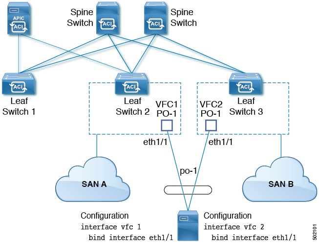
For SAN boot, the host-facing vFC interfaces are bound to port channel members instead of the port channel itself. This binding ensures that the host-side vFC comes up during a SAN boot as soon as the link on the CNA/Host Bus Adapter (HBA) comes up, without relying on the LACP-based port channel to form first.

Figure 1. SAN boot topology with vPC

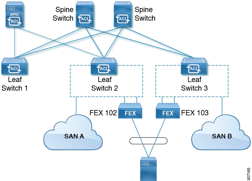
Beginning with Cisco APIC Release 4.0(2), SAN boot is supported through a FEX host interface (HIF) port vPC, as shown in the following figure.

Figure 2. SAN boot topology with a FEX host interface (HIF) port vPC

Guidelines and restrictions for SAN boot with vPC

Consider these limitations when implementing SAN boot with vPC:

  • Multi-member port channels are not supported.

  • If a vFC is bound to a member port, the port channel cannot have more than 1 member.

  • If a vFC is bound to a port channel, the port channel can have only one member port.


Configure SAN boot with VPC using the GUI

Configure SAN Boot with virtual Port Channel (VPC) to provide redundant storage connectivity and ensure high availability for boot operations in a Cisco ACI fabric environment.

To simplify the configuration, this procedure uses the Configure Interface, PC, and VPC wizard in Fabric > Access Policies > Quickstart.

Before you begin

This procedure assumes that the following items are already configured:

  • VSAN Pool

  • VLAN Pool

  • VSAN Attributes, mapping VSANs in the VSAN pool to VLANs

  • Fibre Channel domain (VSAN domain)

  • Tenant, Application Profile

  • Attached Entity Profile

Procedure

  1. Navigate to Fabric > Access Policies > Quickstart and click Configure an interface, PC, and VPC.

  2. In the Configure an interface, PC, and VPC work area, in the VPC Switch Pairs toolbar, click + to create a switch pair.

    1. Enter a number in the VPC Domain ID text box to designate the switch pair.
    2. From the Switch 1 drop-down list, select a leaf switch.

      Only switches with interfaces in the same VPC policy group can be paired together.

    3. From the Switch 2 drop-down list, select a leaf switch.
    4. Click Save to save this switch pair.
  3. In the Configure an interface, PC, and VPC work area, click the large green + to select switches.

    The Select Switches To Configure Interfaces work area opens with the Quick option selected by default.

  4. Select two switch IDs from the Switches drop-down list, and name the switch profile.

  5. Click the large green + again to configure the switch interfaces.

  6. In the Interface Type control, select VPC.

  7. For Interfaces, enter a single port number, such as 1/49, that will be used on both switches as VPC members.

    This action creates an interface selector policy. You can accept or change the name of the policy in the Interface Selector Name text box.

  8. In the Interface Policy Group control, select Create One.

  9. From the Fibre Channel Interface Policy text box, select Create Fibre Channel Interface Policy.

    1. In the Name field, type a name for the Fibre Channel interface policy.
    2. From the Port Mode selector, select F.
    3. From the Trunk Mode selector, select trunk-on.
    4. Click Submit.
  10. From the Port Channel Policy text box, select Create Port Channel Policy.

    1. In the Name field, type a name for the port channel policy.
    2. From the Mode drop-down list, select LACP Active.
    3. From the Control selector, delete Suspend Individual Port.

      Suspend Individual Port must be removed from the port channel; otherwise the physical interface will be suspended when LACP BPDU is not received from the host.

    4. Click Submit.
  11. From the Attached Device Type drop-down list, select Fibre Channel.

  12. From the Fibre Channel Domain drop-down list, select your Fibre Channel domain (VSAN domain).

  13. Click Save to save this VPC configuration.

  14. Click Save to save this interface configuration.

  15. Click Submit.

  16. Expand Tenants > Tenant name > Application Profiles > name > Application EPGs.

  17. Right-click Application EPGs, select Create Application EPG.

    This EPG will be the Native EPG, in which the Native VLAN will be configured.

    1. In the Name field, type a name for the EPG.
    2. From the Bridge Domain drop-down list, select Create Bridge Domain.
    3. In the Name field, type a name for the bridge domain.
    4. From the Type control, select regular.
    5. From the VRF drop-down list, choose the tenant VRF. If no VRF exists yet, select Create VRF, name the VRF and click Submit.
    6. Click Next, Next, and Finish to return to Create Application EPG.
    7. Click Finish.
  18. Expand the Native EPG created in the previous step.

  19. Right-click Static Ports, select Deploy Static EPG On PC, VPC, or Interface.

    1. From the Path Type control, select Virtual Port Channel.
    2. From the Path drop-down list, select the port channel policy created for VPC.
    3. From the Port Encap drop-down list, select VLAN and enter the number of an Ethernet VLAN.
    4. From the Deployment Immediacy control, select Immediate.
    5. From the Mode control, select Access (802.1P).
    6. Click Submit.
  20. Right-click Application EPGs, select Create Application EPG.

    This EPG will be the first of two EPGs, one for each SAN.

    1. In the Name field, type a name for the EPG.
    2. From the Bridge Domain drop-down list, select Create Bridge Domain.
    3. In the Name field, type a name for the bridge domain.
    4. From the Type control, select fc.
    5. From the VRF drop-down list, choose the tenant VRF. If no VRF exists yet, select Create VRF, name the VRF and click Submit.
    6. Click Next, Next, and Finish to return to Create Application EPG.
    7. Click Finish.
  21. Repeat the previous step to create a second application EPG.

    This second EPG will be used for the second SAN.

  22. Expand one of the two SAN EPGs, right-click Fibre Channel (Paths), select Deploy Fibre Channel.

    1. From the Path Type control, select Port.
    2. From the Node drop-down list, select one leaf of your switch pair.
    3. From the Path drop-down list, select the Ethernet port number of your VPC.
    4. In the VSAN text box, type the VSAN number prefixed by "VSAN-".

      For example, type "VSAN-300" for VSAN number 300.

    5. In the VSAN Mode control, select Native.
    6. Click Submit.
  23. Expand the other of the two SAN EPGs and repeat the previous step, selecting the other leaf of your switch pair.
The SAN Boot with VPC configuration is complete. The virtual Port Channel provides redundant storage connectivity across the switch pair, enabling high availability for SAN boot operations in the ACI fabric.


SAN boot with vPC configuration using the CLI

This example assumes that certain items have been configured: a VLAN domain, a tenant with application profile and EPG, and a port channel template "Switch101-102_1-ports-49_PolGrp". In this example, VSAN 200 is bound to physical Ethernet interface 1/49 on leaf 101 and VSAN 300 is bound to physical Ethernet interface 1/49 on leaf 102. The two interfaces are members of virtual port channel Switch101-102_1-ports-49_PolGrp.

This example assumes that these items have been configured:

  • A VLAN domain

  • A tenant, application profile, and an application EPG

  • A port channel template "Switch101-102_1-ports-49_PolGrp"

In this example, VSAN 200 is bound to physical Ethernet interface 1/49 on leaf 101 and VSAN 300 is bound to physical Ethernet interface 1/49 on leaf 102. The two interfaces are members of virtual port channel Switch101-102_1-ports-49_PolGrp.


apic1(config-leaf)# show running-config
# Command: show running-config leaf 101
# Time: Sat Sep  1 12:51:23 2018
  leaf 101
 
    interface ethernet 1/49
      # channel-group Switch101-102_1-ports-49_PolGrp vpc
      switchport trunk native vlan 5 tenant newtenant application AP1 epg epgNative
      port-direction downlink
      exit
 
    # Port-Channel inherits configuration from "template port-channel Switch101-102_1-ports-49_PolGrp"
    interface port-channel Switch101-102_1-ports-49_PolGrp
      exit
 
    interface vfc 1/49
      # Interface inherits configuration from "channel-group Switch101-102_1-ports-49_PolGrp" applied to interface ethernet 1/49
      switchport vsan 200 tenant newtenant application AP1 epg epg200
      exit

apic1(config-leaf)# show running-config            
# Command: show running-config leaf 102
# Time: Sat Sep  1 13:28:02 2018
  leaf 102
    interface ethernet 1/49
      # channel-group Switch101-102_1-ports-49_PolGrp vpc
      switchport trunk native vlan 1 tenant newtenant application AP1 epg epgNative
      port-direction downlink
      exit
 
    # Port-Channel inherits configuration from "template port-channel Switch101-102_1-ports-49_PolGrp"
    interface port-channel Switch101-102_1-ports-49_PolGrp
      exit
 
    interface vfc 1/49
      # Interface inherits configuration from "channel-group Switch101-102_1-ports-49_PolGrp" applied to interface ethernet 1/49
      switchport vsan 300 tenant newtenant application AP1 epg epg300