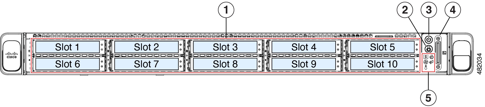
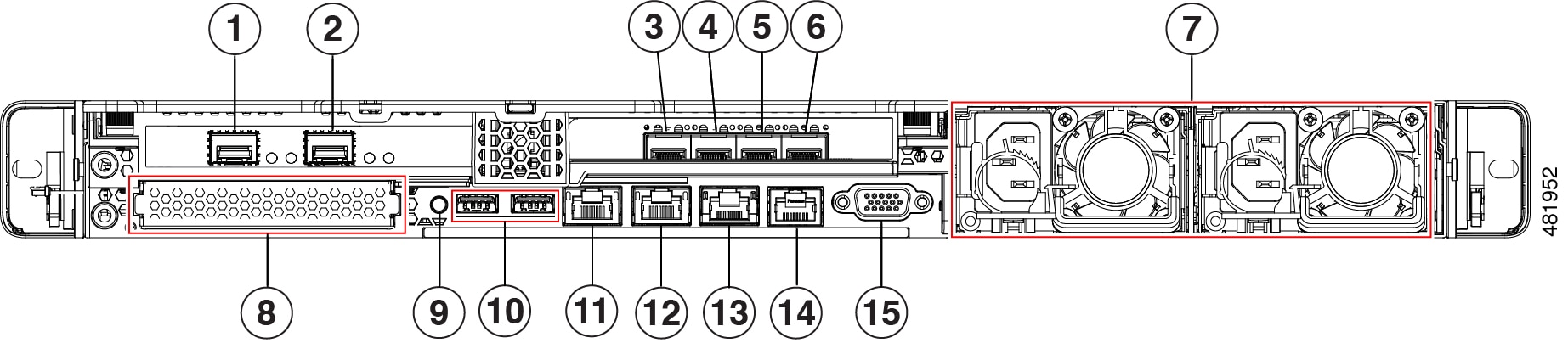
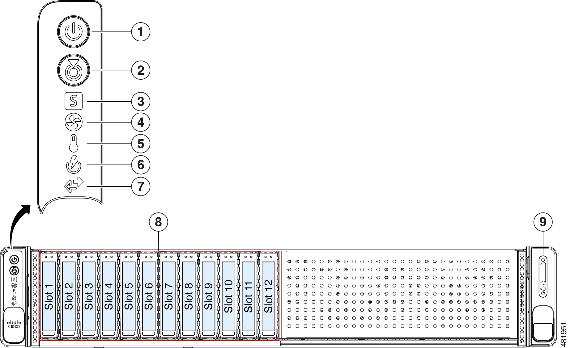
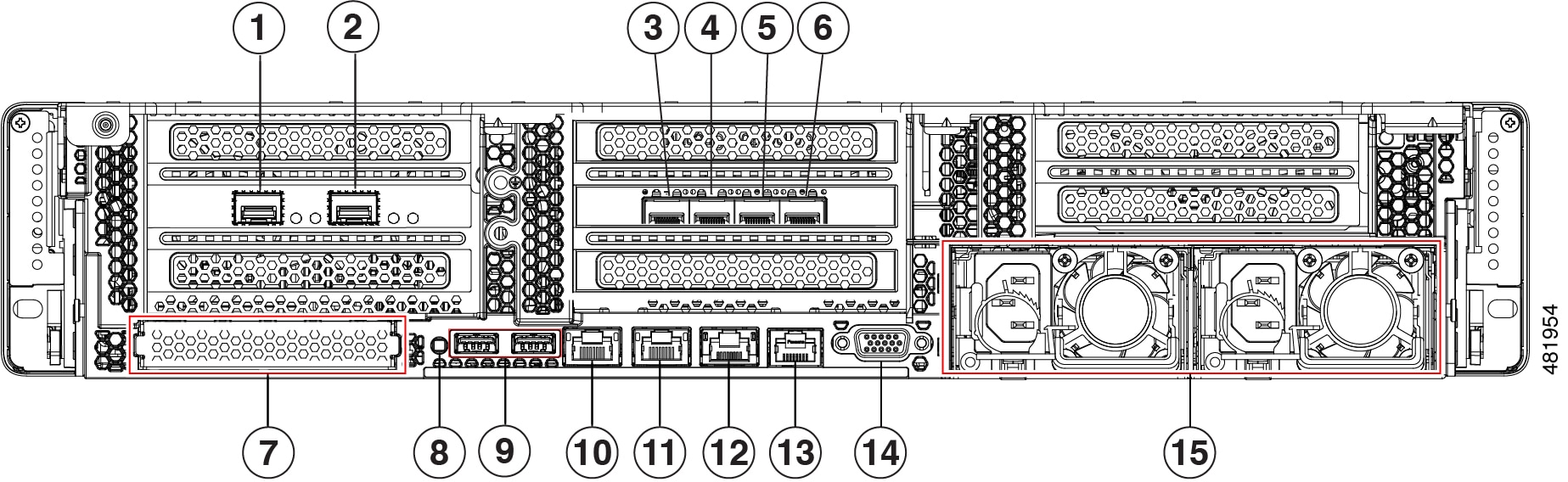
| 1-Gbps/10-Gbps Management Port (Network Adapter 3): This Ethernet port can support 1 Gbps and 10 Gbps, depending on the link partner capability. It is identified as Network Adapter 3 in the Maglev Configuration wizard. Connect this port to a switch that provides access to your enterprise management network. This is the secondary instance of the Management port. It's the fourth port on the Intel E810-XXVDA4 network adapter, in the appliance's PCIe riser 3/slot 3. This port has a link status (ACT) LED and a link speed (LINK) LED. When the link status LED indicates:
-
Off: Link is active, but there is no traffic present.
-
Green, blinking: Traffic is present on the active link.
When the speed LED indicates:
Note
Although capable of operating at lower speeds, this port is intended to operate at 10 Gbps only.
|