|
1. |
Start the Advanced Install configuration wizard:
-
Point your browser to the Cisco IMC IP address you set during the Cisco IMC GUI configuration you performed, then log in to the Cisco IMC GUI as the Cisco IMC user (see Enable browser access to the Cisco Integrated Management Controller).
After successful login, the appliance displays the
Cisco Integrated Management Controller Chassis Summary window, with a blue link menu at the upper right.
-
From the blue link menu, select and then select HTML based KVM.
The KVM console opens in a separate browser window or tab automatically. Use it to monitor the progress of the configuration and respond to Maglev Configuration Wizard prompts.
-
With the KVM displayed, reboot the appliance by making one of these selections:
If asked to confirm your choice to reboot the appliance, click OK.
After displaying reboot messages, the KVM console displays the Static IP Configuration screen.
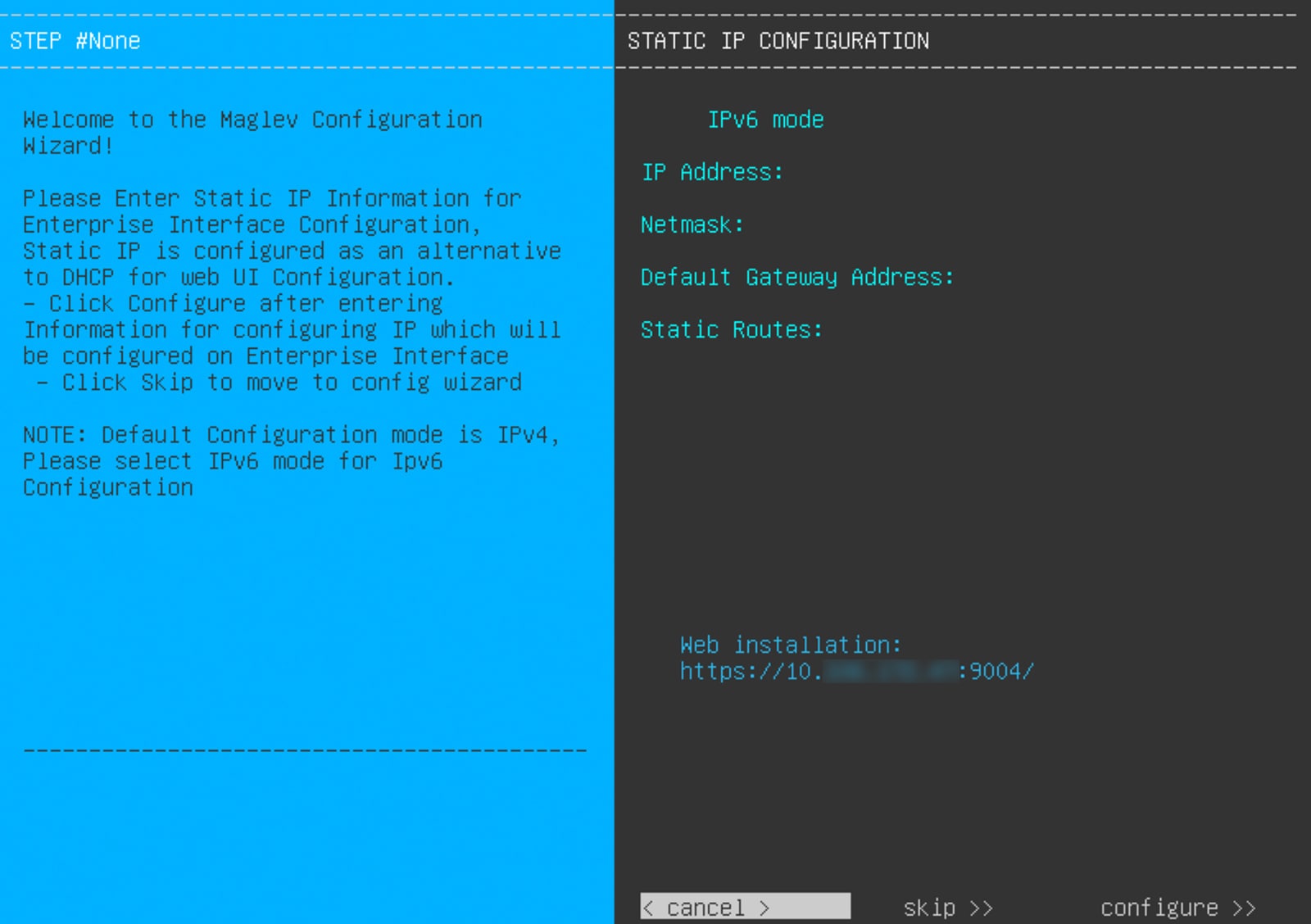
Note the URL listed in the Web Installation field.
-
Do one of these tasks:
-
If you want a DHCP server to assign an IP address, subnet mask, and default gateway to your appliance's enterprise interface, click Skip.
-
If you want to assign your own IP address, subnet mask, and default gateway to your appliance's enterprise interface, enter the information described in this table and then click Configure.
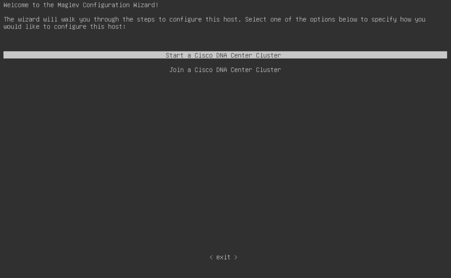
The KVM console displays the Maglev Configuration wizard welcome screen.
-
To bring up the Appliance Configuration screen, open the URL that was displayed in the Static IP Configuration screen.
-
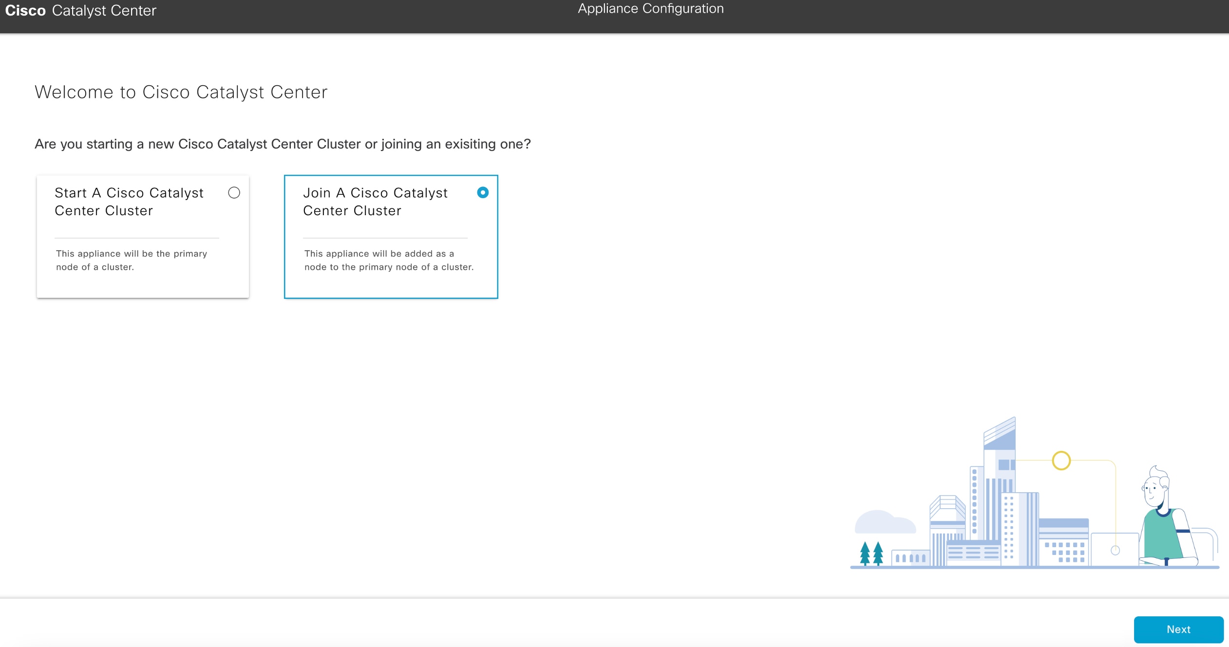
Click the Join a Cisco Catalyst Center Cluster radio button, then click Next.
-
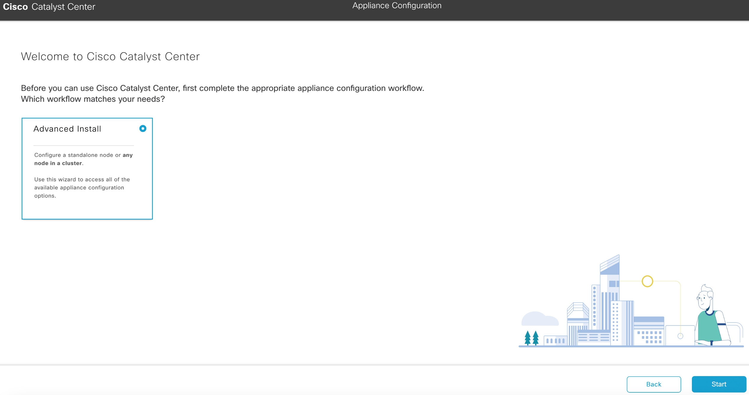
Click the Advanced Install radio button, then click Start.
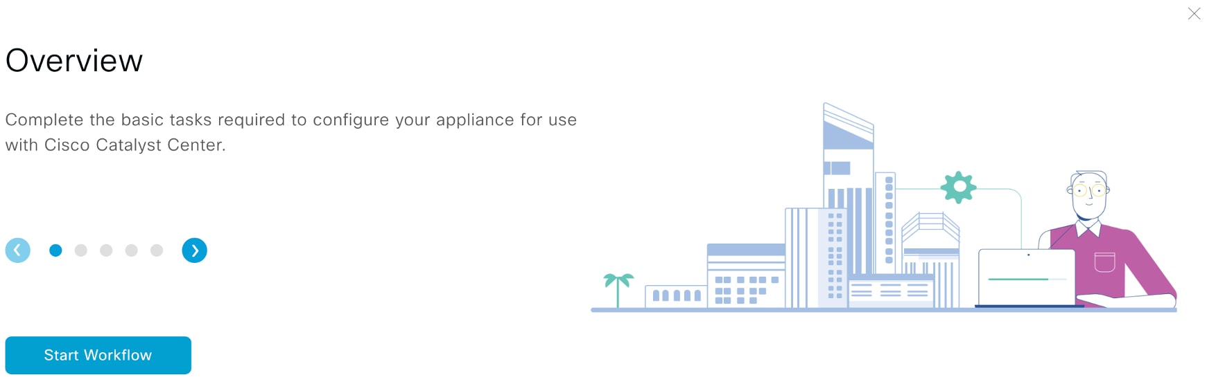
The Overview slider opens. Click > to view a summary of the tasks that the wizard will help you complete.
-
Click Start Workflow to start the wizard.
The Appliance Interface Overview screen opens, providing a description of the four appliance interfaces that you can configure.
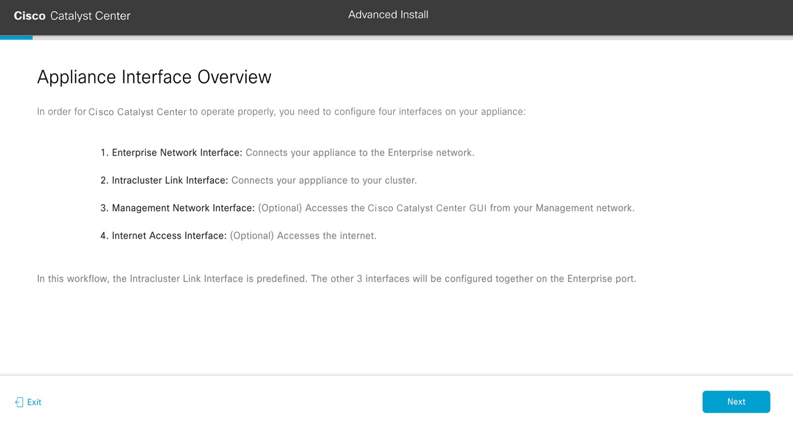
At a minimum, you must configure the interfaces on your appliance's enterprise and cluster ports, as they are required for Catalyst Center functionality. If the wizard fails to display either or both of these ports during the course of configuration, they may be non-functional or disabled. If you discover that they are non-functional, click Exit to exit the wizard immediately. Ensure you have completed all of the steps provided in Execute preconfiguration tasks before resuming configuration or contacting the Cisco Technical Assistance Center (TAC).
|
|
2. |
Complete the Advanced Install configuration wizard:
-
Click Next.
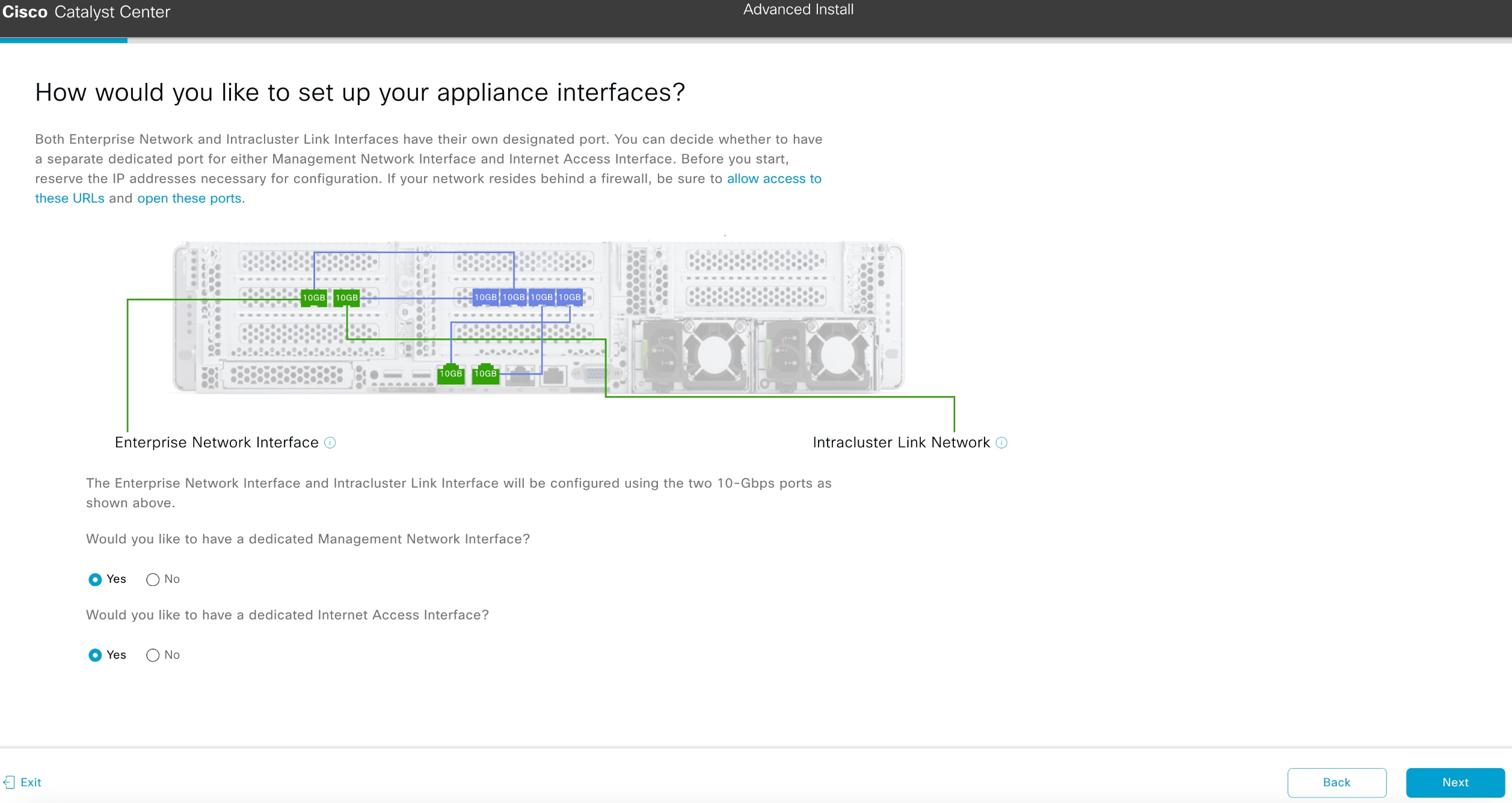
The How would you like to set up your appliance interfaces? screen opens.
-
Indicate whether you want to configure dedicated Management and Internet Access interfaces, then click Next.
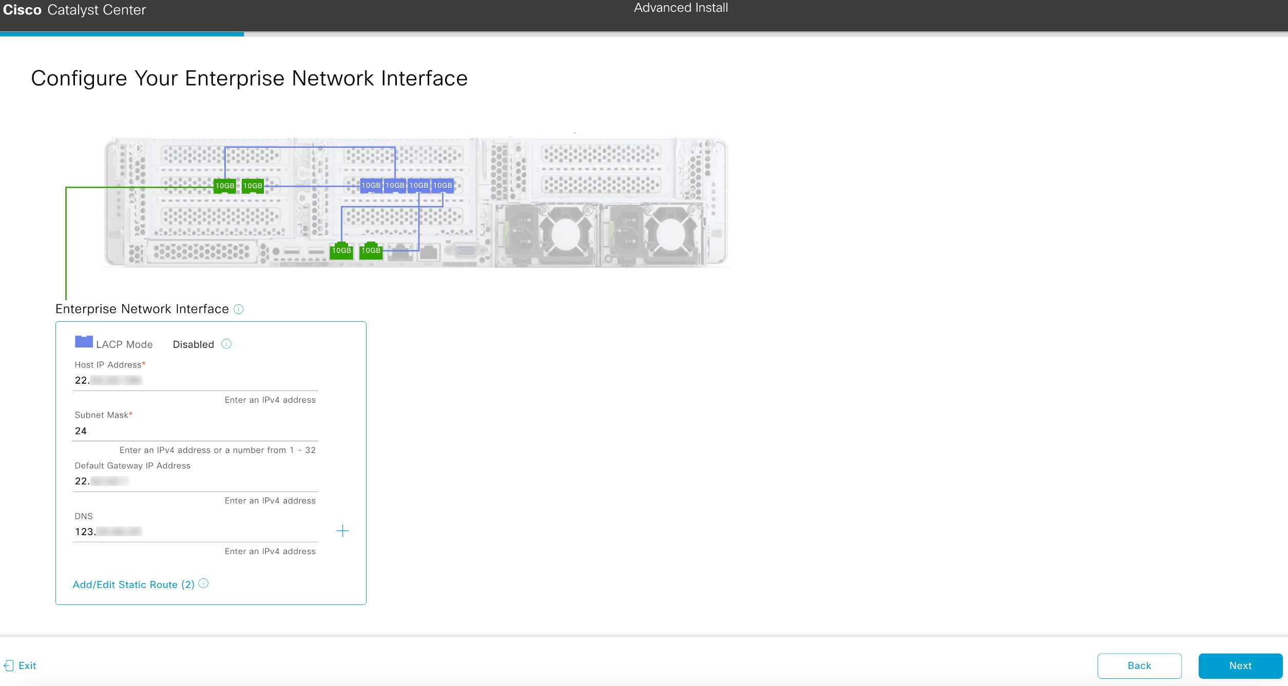
The Configure Your Enterprise Network Interface screen opens.
-
Enter configuration values for the enterprise interface, then click Next.
As explained in Interface cable connections, this is a required interface used to link the appliance to the enterprise network. See Required IP addresses and subnets and Required configuration information for a more detailed description of the values you need to enter.
The wizard validates the information you have entered, confirms that the port is up, and notifies you of any settings that need to be changed before you can continue with the wizard. If the settings you have entered are valid and the port is up, the wizard's Configure Your Intracluster Interface screen opens.
-
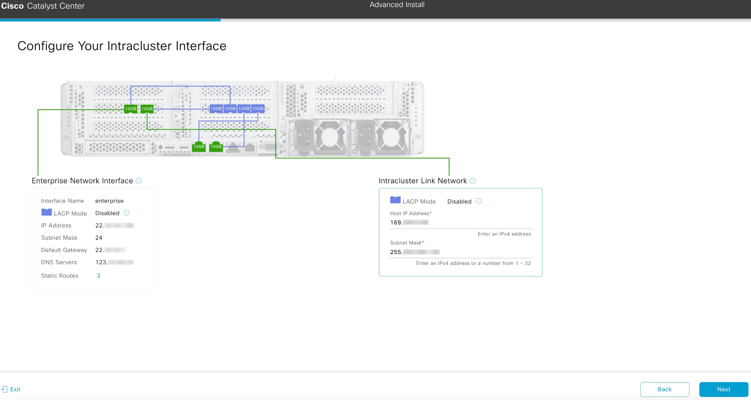
Enter configuration values for your Intracluster interface, then click Next.
As explained in Interface cable connections, this required port is used to link the appliance to your cluster. See Required IP addresses and subnets and Required configuration information for a more detailed description of the values you need to enter.
Note
-
If you opted to configure the enterprise and Internet access interfaces on the same port, complete this step and then continue to Step 2e (which describes how to configure your management interface).
-
If you opted to configure the enterprise and management interfaces on the same port, complete this step and then skip ahead to Step 2f (which describes how to configure your Internet access interface).
-
If you opted to configure the enterprise, management, and Internet access interfaces on the same port, complete this step and then skip ahead to Step 2g.
The wizard validates the information you have entered, confirms that the port is up, and notifies you of any settings that need to be changed before you can continue with the wizard. If the settings you have entered are valid and the port is up, the wizard's Configure Your Management Network Interface screen opens.
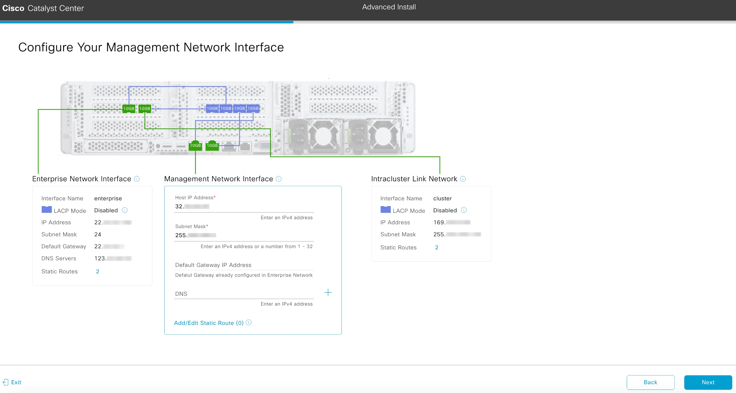
-
(Optional) Enter configuration values for the Management interface, then click Next.
As explained in Interface cable connections, this port is used to access the Catalyst Center GUI from your management network. If you chose to configure a dedicated Management interface, enter the information described in this table. (See Required IP addresses and subnets and Required configuration information for a more detailed description of the values you need to enter.)
Note
If you opted to configure the enterprise and Internet access interfaces on the same port, complete this step and then skip ahead to Step 2g.
The wizard validates the information you have entered, confirms that the port is up, and notifies you of any settings that need to be changed before you can continue with the wizard. If the settings you have entered are valid and the port is up, the wizard's Configure Your Internet Access Interface screen opens.
-
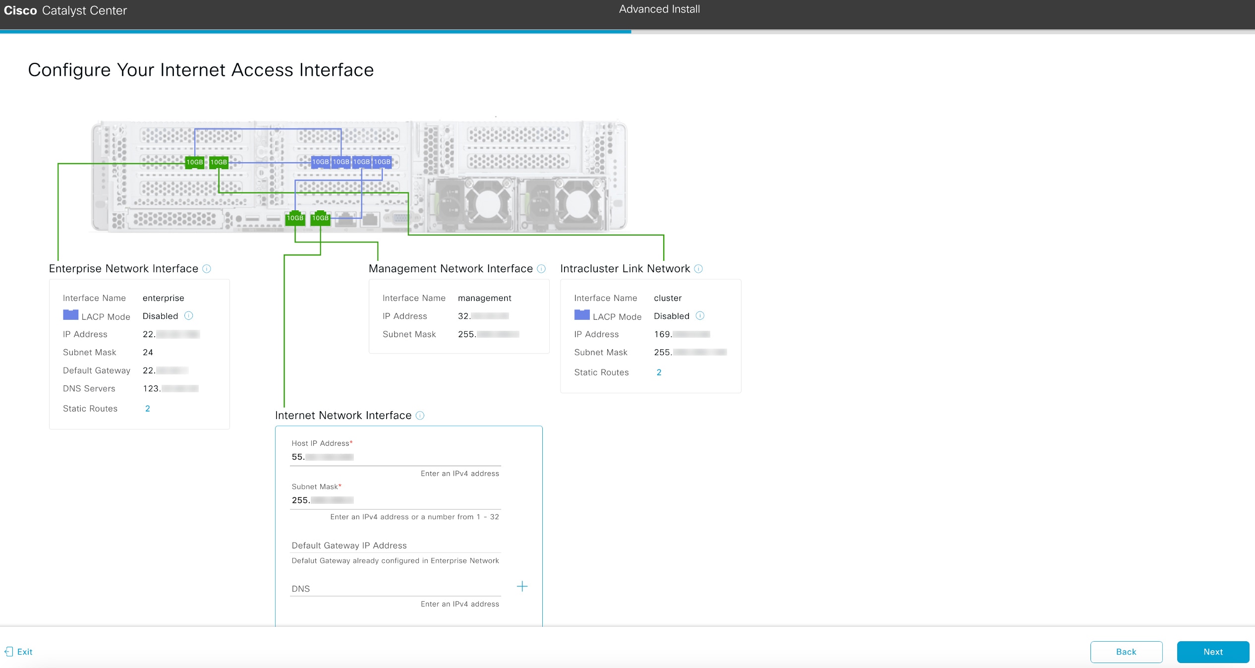
(Optional) Enter configuration values for the Internet Access interface, then click Next.
As explained in Interface cable connections, this is an optional port used to link the appliance to the Internet when you cannot do so through the enterprise port. If you chose to configure a dedicated Internet Access interface, enter the information described in this table. (See Required IP addresses and subnets and Required configuration information for a more detailed description of the values you need to enter.)
The wizard validates the information you have entered, confirms that the port is up, and notifies you of any settings that need to be changed before you can continue with the wizard. If the settings you have entered are valid and the port is up, the wizard's Interface to Port Configuration screen opens.
-
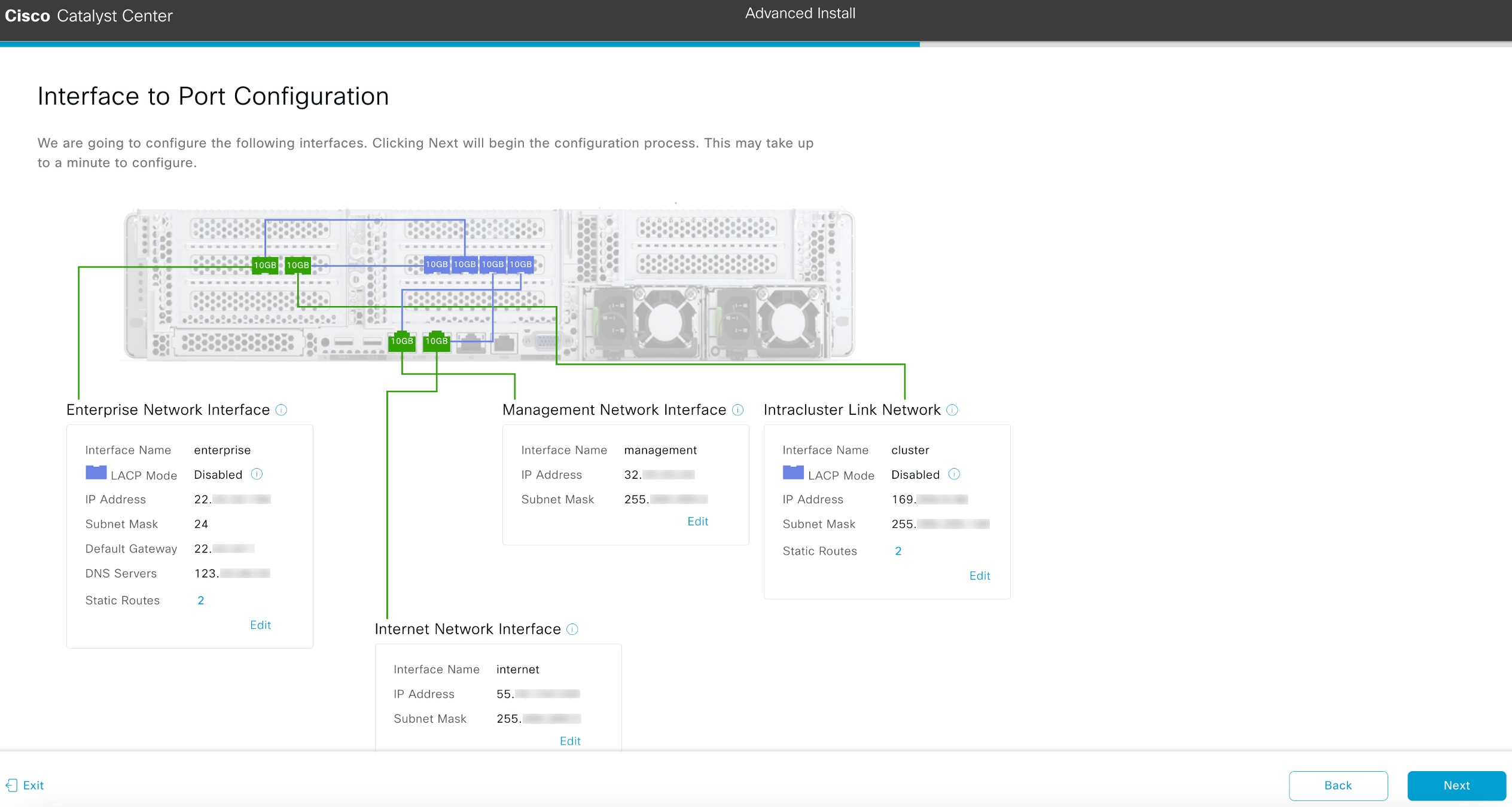
Review the settings that you have entered for the secondary node's interfaces.
If you need to make any changes, click the Edit link for the relevant interface.
-
When you are happy with the interface settings, click Next.
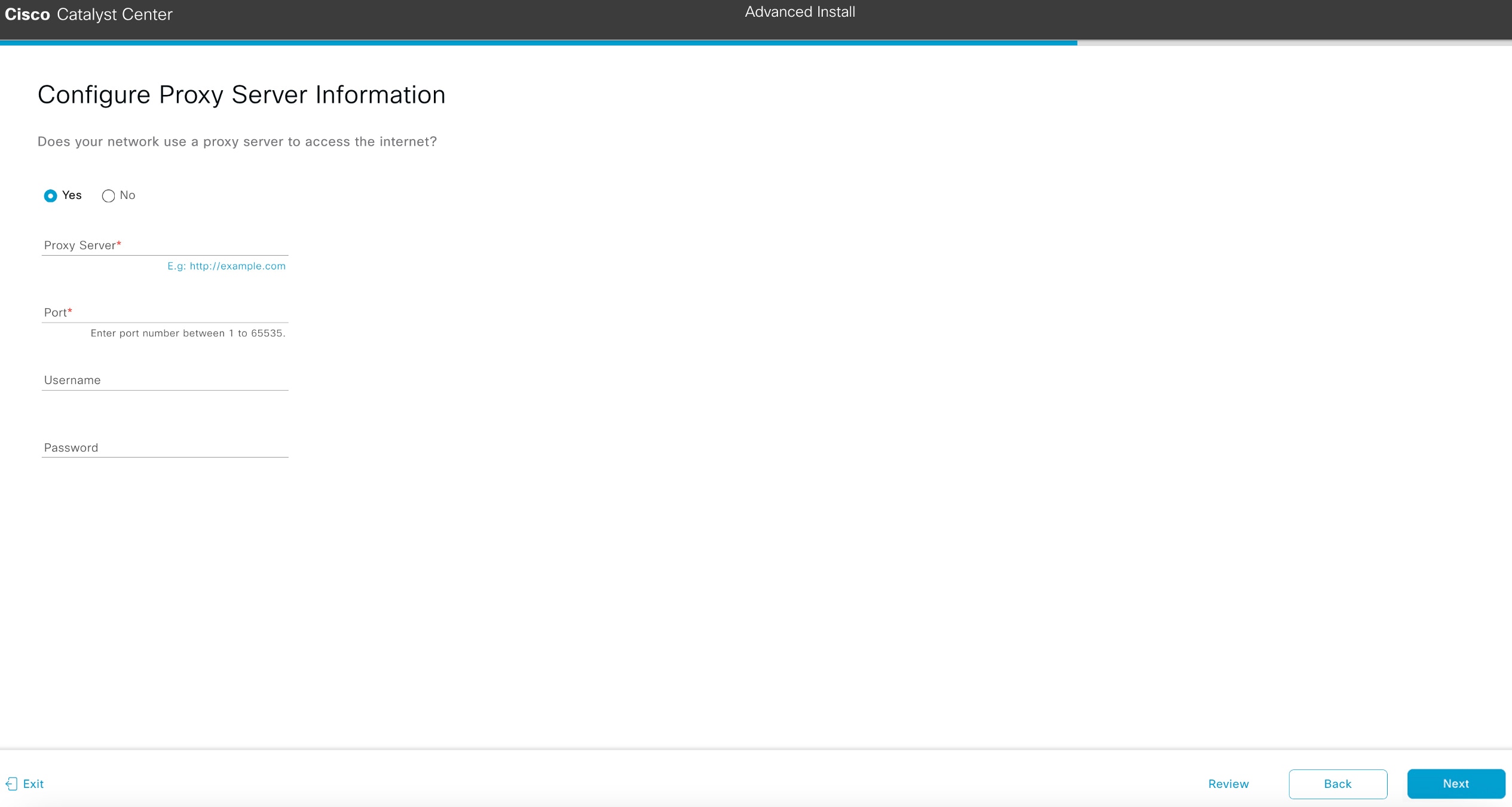
After initial interface configuration has completed, the Configure Proxy Server Information screen opens.
-
Do one of these tasks and then click Next:
-
If your network does not use a proxy server to access the internet, click the No radio button.
-
If your network does use a proxy server to access the internet, enter the values described in this table:
Table 5.
Secondary node entries for proxy server settings
| Proxy Server field |
Enter the URL or host name of an HTTPS network proxy used to access the Internet.
Note
Connection from
Catalyst Center to the HTTPS proxy is supported only via HTTP in this release.
|
| Port field |
Enter the port your appliance used to access the network proxy. |
| Username filed |
Enter the user name used to access the network proxy. If no proxy login is required, leave this field blank. |
| Password field |
Enter the password used to access the network proxy. If no proxy login is required, leave this field blank. |
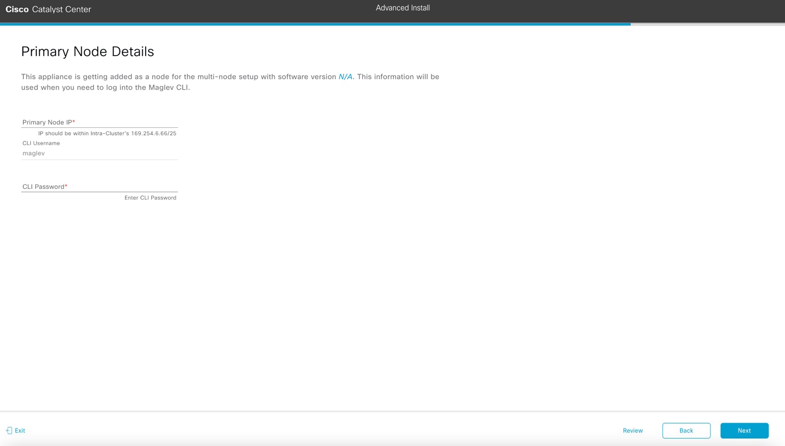
The wizard validates the information you have entered and notifies you of any settings that need to be changed before you can continue with the wizard. If the settings you have entered are valid, the wizard's Primary Node Details screen opens.
-
To establish a connection with your cluster's primary node, enter its IP address and password (by default, the username is already set to maglev) and then click Next.
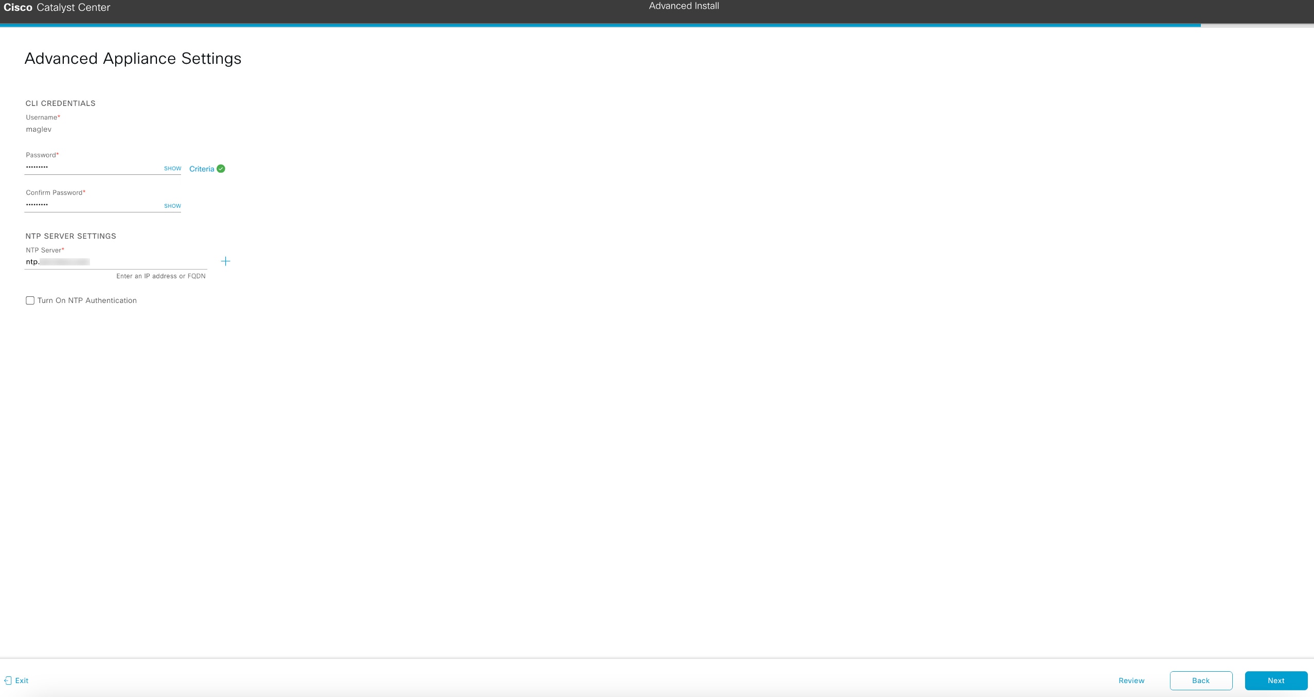
The Advanced Appliance Settings screen opens.
-
Enter configuration values for your cluster, then click Next.
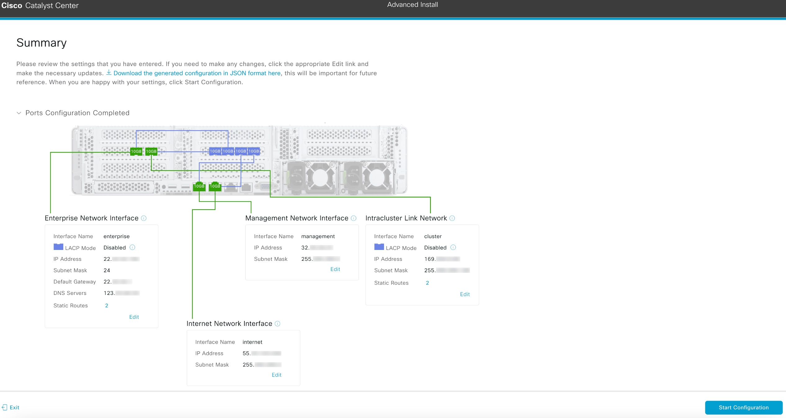
The wizard validates the information you have entered, confirms that the port is up, and notifies you of any settings that need to be changed before you can continue with the wizard. If the settings you have entered are valid, the wizard's Summary screen opens.
Note
To download the appliance configuration as a JSON file, click the here link.
-
Review all of the settings that you have entered while completing the wizard. If necessary, click the appropriate Edit link to open the wizard screen in which you want to make updates.
-
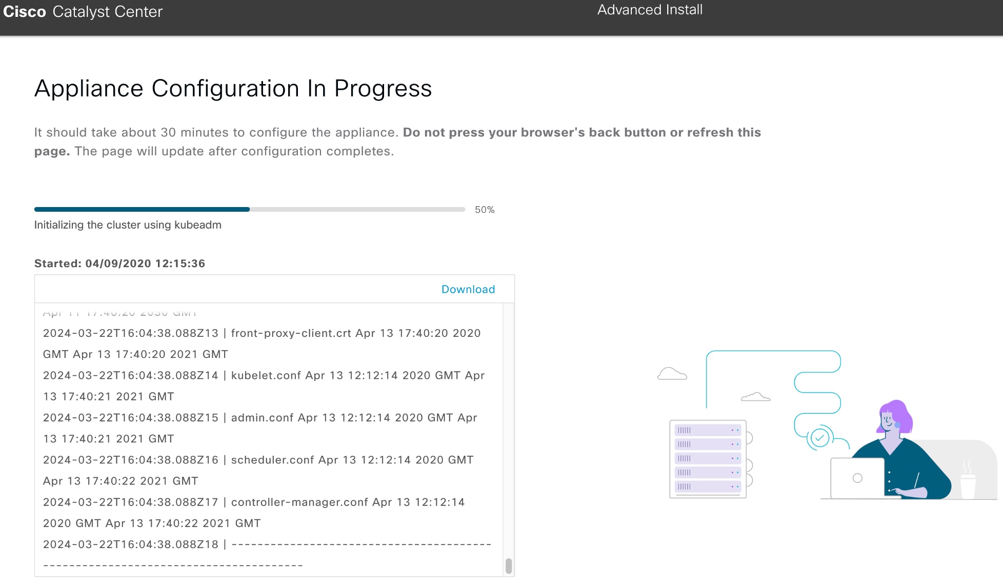
To complete the configuration of your Catalyst Center appliance, click Start Configuration.
The configuration process takes roughly 90 minutes. The wizard screen continuously updates during the process, indicating the tasks that are currently being completed and their progress, as well as any errors that have occurred. To save a local copy of this information as a text file, click the download icon.
|
 ) and choosing .