Cisco Catalyst Center Third-Generation Appliance Installation Guide, Release 3.1.x

PDF

Execute preconfiguration tasks

Want to summarize with AI?

Log in

Overview

Describes the tasks you need to complete to ensure the proper configuration and deployment of the Catalyst Center appliance.

First install the appliance and set up access to the Cisco IMC GUI. See Appliance installation workflow and Enable browser access to the Cisco Integrated Management Controller. Then use Cisco IMC to complete the preconfiguration tasks to ensure correct configuration and deployment.

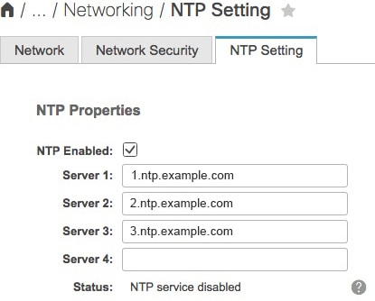
  1. Synchronize the appliance hardware with the Network Time Protocol (NTP) servers that manage your network. Use the same NTP servers whose hostnames or IPs you collected while planning your implementation, as explained in Required IP addresses and subnets. This synchronization is critical for keeping your Catalyst Center data synchronized properly across the network.

  2. Reconfigure the switches connected to the 10 Gbps appliance ports to support higher throughput settings.

Procedure

1.

Log in to the appliance's Cisco IMC using the Cisco IMC IP address, user ID, and password you set in Enable browser access to the Cisco Integrated Management Controller.

If the login is successful, your browser displays the Cisco Integrated Management Controller Chassis Summary window, as shown.
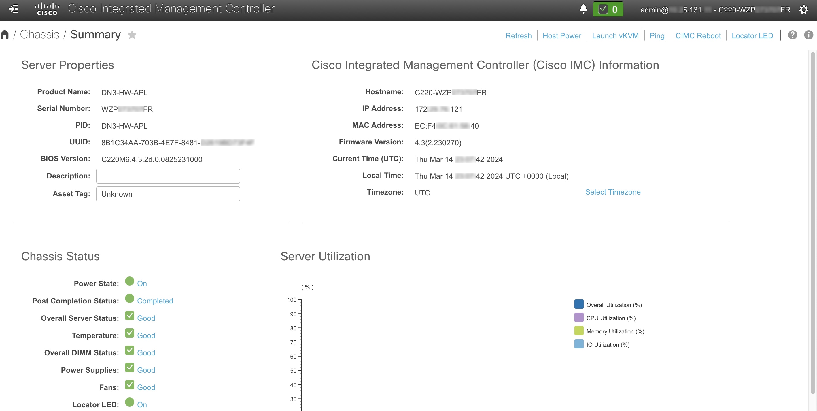
2.

Synchronize the appliance's hardware with the Network Time Protocol (NTP) servers you use to manage your network accordingly:

  1. From the top-left corner of the Cisco IMC GUI, click the Toggle Navigation icon ().

  2. From the Cisco IMC menu, choose Admin > Networking. Select the NTP Setting tab.

  3. Make sure that the NTP Enabled check box is checked, then enter up to four NTP server host names or addresses in the numbered Server fields, as shown.

  4. Click Save Changes. Cisco IMC validates your entries and then begins to synchronize the time on the appliance hardware with the time on the NTP servers.

    Note
    • Third-generation Catalyst Center appliances do not use a virtual interface card (VIC). High throughput is already enabled by default on the network interface card (NIC) installed in your third-generation appliance, so you do not need to configure the NIC in Cisco IMC.

    • You cannot use NTP authentication in Cisco IMC.

3.

Reconfigure your switches to match the high-throughput settings on the appliance accordingly:

  1. Using a Secure Shell (SSH) client, log in to the switch to be configured and enter EXEC mode at the switch prompt.

  2. Configure the switch port.

    On a Cisco Catalyst switch, enter these commands. For example:

    MySwitch#Config terminal
    MySwitch(config)#interface tengigabitethernet 1/1/3 
    MySwitch(config-if)#switchport mode access 
    MySwitch(config-if)#switchport access vlan 99 
    MySwitch(config-if)#speed auto 
    MySwitch(config-if)#duplex full 
    MySwitch(config-if)#mtu 1500 
    MySwitch(config-if)#no shut 
    MySwitch(config-if)#end 
    MySwitch(config)#copy running-config startup-config 

    On a Cisco Nexus switch, enter these commands to disable Link Layer Discovery Protocol (LLDP) and priority flow control (PFC). For example:

    N7K2# configure terminal
    N7K2(config)# interface eth 3/4
    N7K2(config-if)# no priority-flow-control mode auto
    N7K2(config-if)# no lldp transmit
    N7K2(config-if)# no lldp receive
    Note
    • These commands are examples only.

    • The switch port on Catalyst Center third-generation appliances must be set to access mode for proper operation. Trunk mode is not supported.

  3. Run the show interface tengigabitethernet portID command. Verify that the port is connected, running, and has the correct MTU, duplex, and link-type settings in the command output. For example:

    MySwitch#show interface tengigabitethernet 1/1/3 
    TenGigabitEthernet1/1/3 is up, line protocol is up (connected) 
      Hardware is Ten Gigabit Ethernet, address is XXXe.310.8000 (bia XXX.310.8000)
      MTU 1500 bytes, BW 10000000 Kbit/sec, DLY 10 usec, 
         reliability 255/255, txload 1/255, rxload 1/255 
      Encapsulation ARPA, loopback not set 
      Keepalive not set 
      Full-duplex, 10GB/s, link type is auto, media type is SFP-10Gbase-SR
  4. Run the show run interface tengigabitethernet portID command to configure the switch ports where the cables from the Intel X710-DA2 NIC ports are connected. For example:

    MySwitch#show run interface tengigabitethernet 1/1/3 
    Building configuration... 
    Current configuration : 129 bytes 
    ! interface TenGigabitEthernet1/1/3 
     switchport access vlan 99 
     ip device tracking maximum 10 
    end 
    
    MySwitch#
  5. Run the show mac address-table interface tengigabitethernet portID command and verify the MAC address from the command output. For example:

    MySwitch#show mac address-table interface tengigabitethernet 1/1/3 
               Mac Address Table 
    ––––––––––––––––––––––––––––––––––––––––––-- 
    Vlan     Mac Address       Type      Ports 
    ––--     ––––––––––-       –––-      –––-- 
    99       XXXe.3161.1000    DYNAMIC   Te1/1/3 
    Total Mac Addresses for this criterion: 1 
    
    MySwitch#
4.

In the Configured Boot Mode drop-down list, confirm that Legacy (the default mode) is set.

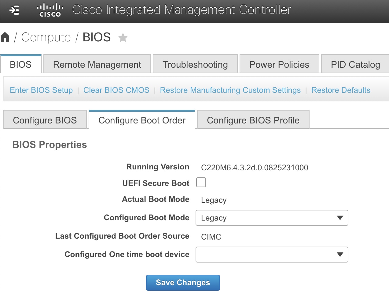
To access the Configure Boot Order tab:

  1. From the top-left corner of the Cisco IMC GUI, click the Toggle Navigation icon ().

  2. From the Cisco IMC menu, choose Compute > BIOS > Configure Boot Order.

Caution

Keep the Legacy boot mode setting . The UEFI boot mode setting may cause your Catalyst Center appliance interfaces not to respond to pings.

What to do next

After completing this task, do one of these tasks: