SD-WAN

This chapter describes the SD-WAN capabilities supported in the management center.

SD-WAN Capabilities

Software-Defined WAN (SD-WAN) solutions replace traditional WAN routers and are agnostic to WAN transport technologies. SD-WAN provides dynamic, policy-based, application path selection across multiple WAN connections and supports service chaining for additional services such as WAN optimization and firewalls.

As organizations expand their operations across multiple branch locations, ensuring secure and streamlined connectivity becomes paramount. Deploying a secure branch network infrastructure involves complex configurations, which can be time-consuming and prone to configuration errors if not handled properly. However, organizations can overcome these challenges by leveraging the Cisco Secure Firewall Management Center (management center) and the Cisco Secure Firewall Threat Defense (threat defense) devices for a simplified and secure branch deployment.

In this guide, we explore the concept of simplifying secure branch deployment using a robust firewall solution. By integrating a secure firewall as a foundational component of the branch network architecture, organizations can establish a strong security baseline while simplifying the deployment process. This approach enables organizations to enforce unified security policies, optimize traffic routing, and ensure resilient connectivity.

Some of the SD-WAN capabilities supported on the Cisco Secure Firewall are:

  • Simplified management:

    • SD-WAN Wizard

    • SASE: Umbrella auto tunnel deployment

    • Dynamic VTI (DVTI) hub spoke topology simplification

  • Application awareness:

    • Direct Internet Access (DIA) for public cloud and guest user

    • Policy based routing (PBR) using applications as a match criteria

    • Local tunnel ID support for Umbrella

  • Increased usable bandwidth:

    • ECMP support for load balancing across multiple ISPs and VTIs

    • Application-based load balancing using PBR

  • High availability with near zero network downtime:

    • Dual ISP configuration

    • Optimal path selection based on application-based interface monitoring.

  • Secure Elastic Connectivity:

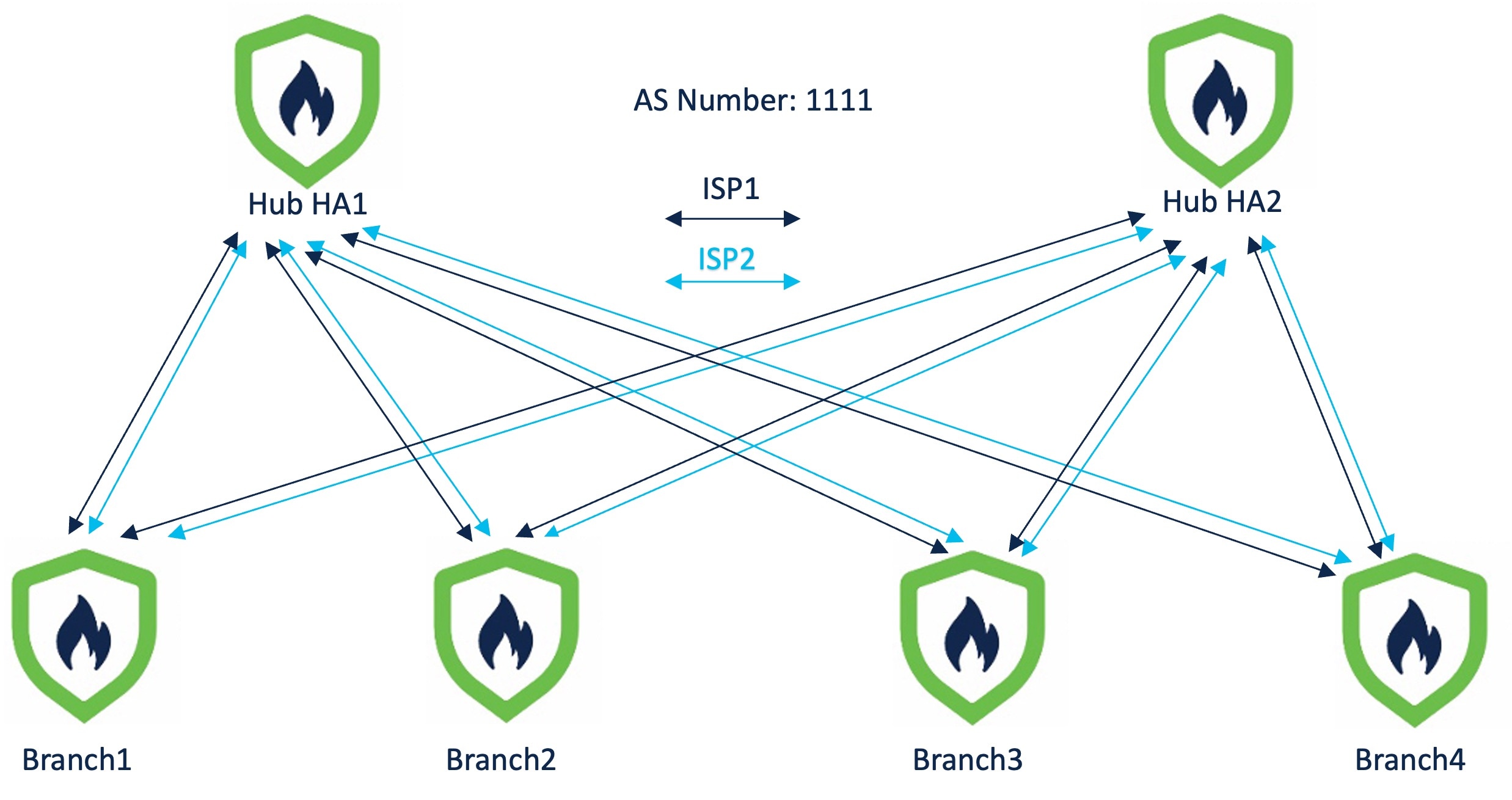
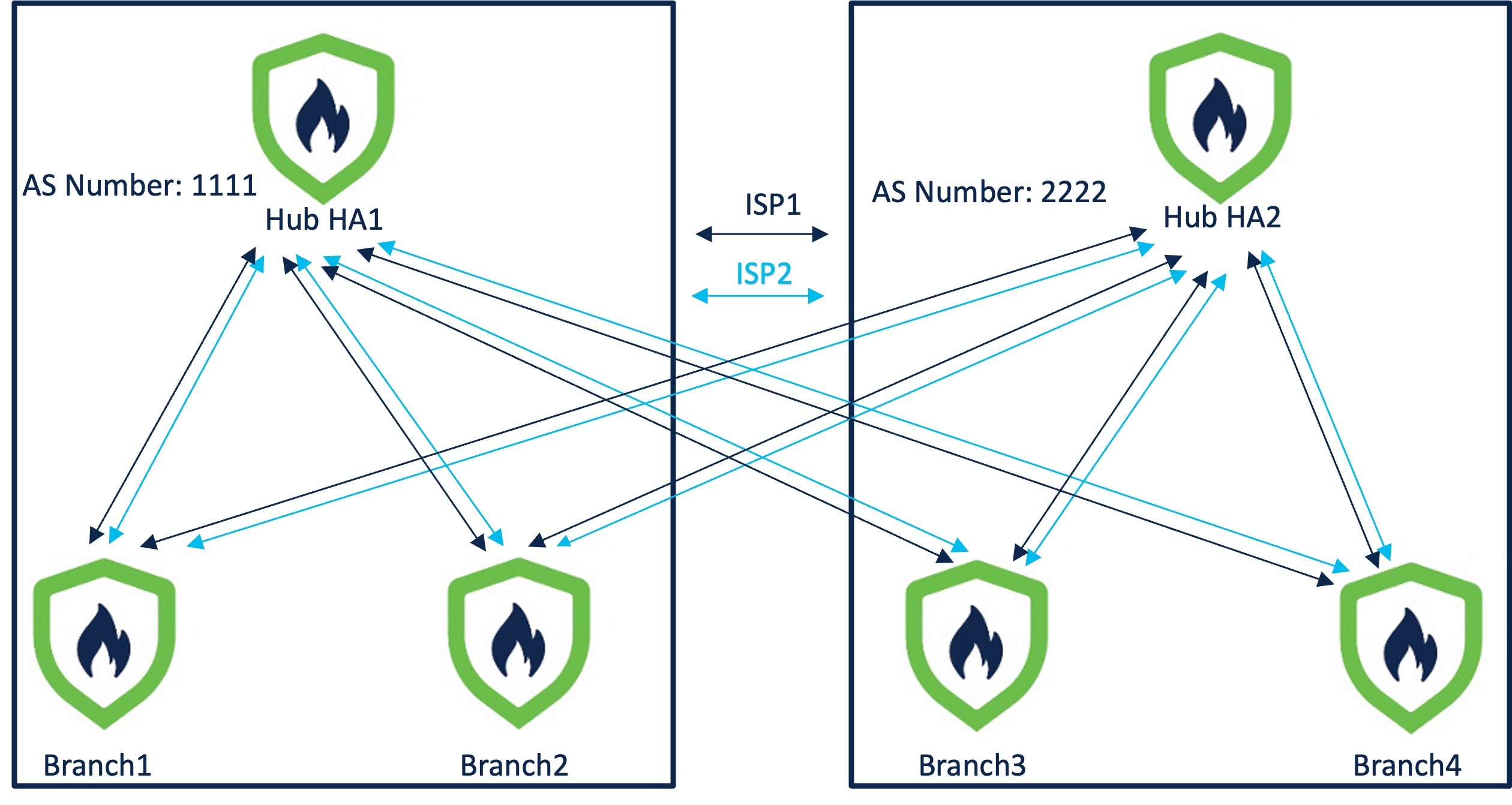
    • Route-based (VTI) VPN tunnels between headquarters (hub) and branches (spokes)

    • IPv4 and IPv6 BGP, IPv4 and IPv6 OSPF, and IPv4 EIGRP over VTI

    • DVTI hubs that support spokes with static or dynamic IP

Features

The following table lists some commonly used SD-WAN features:

Feature

Introduced in

More Information

Configure settings to carry SGT over the SD-WAN tunnels using SD-WAN wizard.

Release 10.0

Using SD-WAN Wizard for Secure Branch Network Deployment

Support for ECMP in hubs and BFD for SVTI and DVTI.

Release 10.0

Using SD-WAN Wizard for Secure Branch Network Deployment

Use PBR to handle traffic based on advanced custom application detector.

Release 10.0

Policy Based Routing

Management of Remote Branch (HA) with Dual WAN Support

Release 7.7

SD-WAN Summary Dashboard

PBR Support for Custom Applications

Release 7.7

Policy Based Routing

SD-WAN Wizard

Release 7.6

Using SD-WAN Wizard for Secure Branch Network Deployment

Application monitoring using SD-WAN Summary dashboard

Release 7.4.1

SD-WAN Summary Dashboard

SD-WAN Summary Dashboard

Release 7.4

SD-WAN Summary Dashboard

Policy-based routing with user identity and SGTs

Release 7.4

Policy Based Routing

Policy-based routing using HTTP path monitoring

Release 7.4

Policy Based Routing

Loopback interface support for VTIs

Release 7.3

About Loopback Interfaces

Support for dynamic VTI (DVTI) with site-to-site VPN

Release 7.3

Dynamic VTI

Umbrella auto tunnel

Release 7.3

Deploy a SASE Tunnel on Umbrella

Support for IPv4 and IPv6 BGP, IPv4 and IPv6 OSPF, and IPv4 EIGRP for VTIs

Release 7.3

BGP

OSPF

EIGRP

Route-based site-to-site VPN with hub and spoke topology

Release 7.2

Create a Route-based Site-to-Site VPN

Policy-based routing with path monitoring

Release 7.2

Policy Based Routing

Site to Site VPN Monitoring Dashboard

Release 7.1

Monitor Site-to-Site VPNs Using Site-to-Site VPN Dashboard

Direct Internet Access/Policy Based Routing

Release 7.1

Policy Based Routing

Equal-Cost-Multi-Path (ECMP) zone with WAN interfaces

Release 7.1

ECMP

ECMP zone with VTI interfaces

Release 7.1

ECMP

Backup VTI for route-based site-to-site VPN

Release 7.0

Route Traffic Through a Backup VTI Tunnel

Support for static VTI (SVTI) with site-to-site VPN

Release 6.7

Static VTI

Using SD-WAN Wizard for Secure Branch Network Deployment

Management Center allows you to easily configure VPN tunnels and routing configuration between your centralized headquarters (hubs) and remote branch sites (spokes) using the new SD-WAN wizard.

What are Hubs and Spokes?

Hubs: Devices that enable secure VPN connectivity to and from one or more remote branch devices or spokes. Hubs also act as a gateway for spokes to communicate with each other.

Spokes: Devices in remote branches that connect over VPN to a hub to securely access the corporate resources behind the hub. Spokes communicate with each other through the hub.

Benefits of Using SD-WAN Wizard

  • Simplifies and automates the VPN and routing configuration of your SD-WAN network.

  • Creates route-based VPN tunnels and simplifies the configuration process by automating tasks such as:

    • Generating tunnel interfaces of the branches.

    • Assigning IP addresses to the tunnel interfaces.

    • Configuring BGP for the SD-WAN overlay network. These configurations ensure seamless connection between hubs and spokes, and spoke to spoke through the hub.

  • Provides seamless routing because hubs act as route reflectors and enable the following:

    • Provide connectivity between the spokes.

    • Determine the best routing path based on the spokes’ active and backup tunnels.

  • Requires minimal user input.

  • Easily add multiple branches at a time.

  • Provides easy dual ISP configurations.

  • Enables network scaling.

Guidelines and Limitations for Using SD-WAN Wizard

Guidelines

  • When you configure the DVTIs of two hubs, ensure that they have the same IPsec tunnel mode (IPv4 or IPv6).

  • In a dual-hub SD-WAN topology, the hubs can be in different geographic locations and have different protected networks behind them. To ensure direct communication between these networks, ensure that you configure the following:

    • A point-to-point route-based VPN topology between the two hubs (Secure Connections > Site-to-Site VPN & SD-WAN, and click Add > Route-Based VPN).

    • A dynamic routing protocol between the hubs (Devices > Device Management, click the device name and click Routing).

  • When you configure IP address pools for spokes, ensure the following:

    • The Allow Overrides check box must be unchecked.

    • If you are using multiple pools, the IP addresses of the pools must not overlap.

    • IP addresses must not overlap with any of the interfaces on the spoke.

  • When you create security zones or interface groups, choose Routed as the Interface Type.

  • Use the spoke security zone to configure an access control policy that allows tunnel traffic to and from the spokes.

  • Configure the spokes' static VTIs in an ECMP zone to load balance the application traffic. If you do not configure the ECMP zone, the remaining paths act as backup paths when the primary path goes down. Note that you must configure the spokes' static VTIs and not the physical interfaces in the ECMP zone. This configuration is not part of the SD-WAN wizard.

  • In SD-WAN topologies with dual ISPs on spokes, the tunnel identity and the tunnel source of the spokes must be unique.

  • If a spoke is part of multiple SD-WAN topologies, ensure that you use the same local community tag and learned route community tag in each SD-WAN topology. Note that the local community tags and learned route community tags must be different from each other.

  • If a device has only IPv6 address configurations, you must configure the BGP router ID with a loopback or physical interface that has an IPv4 address (Devices > Device Management, and click Routing > General Settings > BGP). ​

  • Configure unique local IKE identity for all tunnels across all your SD-WAN VPN topologies.

  • Ensure that the spokes in an SD-WAN topology do not have the same protected network.

  • Use distinct DVTIs for SD-WAN and route-based VPNs to avoid IPsec profile conflicts and errors.

  • Ensure that you shutdown a DVTI virtual template before you change the IP address of a DVTI’s numbered interface.

Limitations

  • You can configure a maximum of two hubs in an SD-WAN topology using the SD-WAN wizard.

  • For each spoke, you can use only one WAN interface per topology. However, for dual-ISP setups, you can configure a second SD-WAN topology with the second WAN interface. For more information, see Sample Configurations for Dual ISP Deployment Using SD-WAN Wizard.

  • SD-WAN wizard does not support the following:

    • IKEv1

    • Cluster devices are not supported on the hub and spoke because VTI is not supported on cluster devices.

    • Extranet hubs and spokes such as ASA, Cisco IOS, Cisco Viptela, Umbrella, Meraki, or vendor devices.​

License Requirements for Configuring an SD-WAN Topology

Ensure that export-controlled features are enabled in your Smart License to configure an SD-WAN topology in Firewall Management Center.

To verify if export-controlled functionality is enabled for your Smart License account, choose Administration > Licenses > Smart Licenses.

Prerequisites for Using the SD-WAN Wizard

  • You must be an Admin user.

  • Hub devices must be Version 7.6.0 and later.

  • Spoke devices must be Version 7.3.0 and later.

  • The Firewall Threat Defense devices must have an internet-routable public IP address. The IP address can be static or dynamic.

  • Assign appropriate logical names and IP addresses to the interfaces of the Firewall Threat Defense devices. For example, use inside for the interface connected to the LAN, and outside for the interface connected to the internet or WAN.

  • If you are using certificate-based authentication, you must enroll the certificates in the hub and spokes.

  • Configure routing, NAT, and AC policies to ensure underlay connectivity between the devices.

  • Hub devices must be Version 10.0 and later to enable ECMP on the virtual access interfaces associated with the hub’s dynamic VTI.

  • Firewall Threat Defense devices must be Version 10.0 and later to enable BFD routing protocol on SVTIs and DVTIs.

Configure an SD-WAN Topology Using the SD-WAN Wizard

The SD-WAN wizard allows you to easily configure VPN tunnels between your centralized headquarters and remote branch sites.

Before you begin

Ensure that you review Prerequisites for Using the SD-WAN Wizard and Guidelines and Limitations for Using SD-WAN Wizard.

Procedure


Step 1

Choose Secure Connections > Site-to-Site VPN & SD-WAN, and click Add.

Step 2

Enter a name for the SD-WAN VPN topology in the Topology Name field.

Step 3

Click the SD-WAN Topology radio button and click Create.

Step 4

Configure a hub:

  1. Click Add Hub.

  2. From the Device drop-down list, choose a hub.

  3. Click + next to the Dynamic Virtual Tunnel Interface (DVTI) drop-down list to add a dynamic VTI for the hub.

    The Add Virtual Tunnel Interface dialog box is prepopulated with default configurations. However, you must configure the Tunnel Source, and the Borrow IP Address. For more information, see Add a Dynamic Virtual Tunnel Interface for a Hub.

  4. Click OK.

  5. In the Hub Gateway IP Address field, enter the public IP address of the hub's VPN interface or the tunnel source of the dynamic VTI to which the spokes connect.

    This IP address is auto populated if the interface has a static IP address. If hub is behind a NAT device, you must manually configure the post-NAT IP address.

  6. From the Spoke Tunnel IP Address Pool drop-down list, choose an IP address pool or click + to create an address pool.

    When you add spokes, the wizard auto generates spoke tunnel interfaces, and assigns IP addresses to these spoke interfaces from this IP address pool.

  7. Click Add to save the hub configuration.

  8. (Optional) To add a secondary hub, repeat Step 4a to Step 4f.

  9. Check the ECMP check box to enable Equal Cost Multi-Path (ECMP) on the dynamic VTIs of hub devices with Version 10.0 or later.

    All virtual access interfaces on the hub connecting to the same spoke are grouped into an ECMP zone. This feature load balances traffic through multiple paths to a spoke.​

  10. Click Next.

Step 5

Configure spokes:

Click Add Spoke to add a single spoke device, or click Add Spokes (Bulk Addition) to add multiple spokes to your topology.

  • Click Add Spoke. In the Add Spoke dialog box, configure the following parameters:

    1. From the Device drop-down list, choose a spoke.

    2. From the VPN Interface drop-down list, choose a WAN-facing or internet-facing physical interface to establish a VPN connection with the hub.

    3. Check the Local Tunnel (IKE) Identity check box to enable a unique and configurable identity for the VPN tunnel from this device to the remote peer. By default, this option is enabled.

    4. Choose one of the following options from the Identity Type drop-down list:

      • Key ID—(Default value) This value is auto populated as <sd-wan topologyname>_<device_IP_address>, for example, sdwantopo1_192.168.0.200. You can also specify a key ID of your choice.

      • Email ID—Specify an email ID up to 127 characters.

      • IP Address—IP address of the spoke's VPN interface.

      • Auto—IP address of the spoke's VPN interface for pre-shared key authentication or the certificate Distinguished Name (DN) for certificate-based authentication.

      • Hostname—Fully qualified hostname of the spoke.

    5. Click Save to save the spoke configuration.

  • Click Add Spokes (Bulk Addition). In the Add Bulk Spokes dialog box, configure the following parameters:

    1. Choose one or more devices from the Available Devices list and click Add to move the devices to Selected Devices.

    2. Use one of the following methods to select the VPN interfaces of the spokes:

      • Click the Interface Name Pattern radio button and specify a string to match the logical name of the internet or WAN interface of the spokes, for example, outside*, wan*.

        If the spoke has multiple interfaces with the same pattern, the first interface that matches the pattern is selected for the topology.

      • Click the Security Zone radio button and choose a security zone with the VPN interfaces of the spokes from the drop-down list, or click + to create a security zone.

    3. Click Next.

      The wizard validates if the spokes have interfaces with the specified pattern. Only the validated devices are added to the topology.

    4. Click Add.

    5. Click Next.

For each spoke, the wizard automatically selects the hub's DVTI as the tunnel source IP address.

Note


If the hub’s tunnel source IP address is an IPv6 address, the wizard automatically selects the first IPv6 address of the spokes' selected interface.​ To edit the IPv6 address of a spoke's tunnel source, click the edit icon next to a spoke, choose an IPv6 address from the IP Address drop-down list, and click Save.

Step 6

Configure authentication settings for the devices in the SD-WAN topology:

  1. Authentication Type—For device authentication, you can use a manual pre-shared key, an auto-generated pre-shared key, or a certificate.

    • Pre-shared Manual Key—Specify the pre-shared key for the VPN connection.

    • Pre-shared Automatic Key—(Default value) The wizard automatically defines the pre-shared key for the VPN connection. Specify the key length in the Pre-shared Key Length field. The range is 1 to 127.

    • Certificate—When you use certificates as the authentication method, the peers obtain digital certificates from a CA server in your PKI infrastructure, and use them to authenticate each other.

  2. Choose one or more algorithms from the Transform Sets drop-down list.

  3. Choose one or more algorithms from the IKEv2 Policies drop-down list.

  4. Click Next.

Step 7

Configure the SD-WAN settings:

This step involves the auto generation of spoke tunnel interfaces, and BGP configuration of the overlay network.

  1. From the Spoke Tunnel Interface Security Zone drop-down list, choose a security zone or click + to create a security zone to which the wizard automatically adds the spokes' auto-generated Static Virtual Tunnel Interfaces (SVTIs).

  2. Check the Enable BGP on the VPN Overlay Topology check box to automate BGP configurations such as neighbor configurations between the overlay tunnel interfaces and basic route redistribution from the directly connected LAN interfaces of the hubs and spokes.

  3. In the Autonomous System Number field, enter an Autonomous System (AS) number.

    AS number is a unique number for a network with a single routing policy. BGP uses AS numbers to identify networks. The spoke's BGP neighbor configuration is generated based on the corresponding hub’s AS number. Range is from 0 to 65536.

    • If all the hubs and spokes are in the same region, by default, 64512 is the AS number.

    • If the primary and secondary hubs are in different regions, the primary hub and the spokes are configured with 64512 as the AS number, and the secondary hub is configured with a different AS number.

  4. In the Community Tag for Local Routes field, enter the BGP community attribute to tag connected and redistributed local routes. This attribute enables easy route filtering.

  5. Check the Redistribute Connected Interfaces check box and choose an interface group from the drop-down list or click + to create an interface group with connected inside or LAN interfaces for BGP route redistribution in the overlay topology.

  6. Check the Enable Multiple Paths for BGP check box to allow multiple BGP routes to be used at the same time to reach the same destination. This option enables BGP to load-balance traffic across multiple links.

    Note that when you enable this option, BGP multipath is enabled only for spokes.

  7. (Optional) Check the Secondary Hub is in Different Autonomous System check box. This check box appears only if you have a secondary hub in this topology.

  8. In the Autonomous System Number field, enter the AS number for the secondary hub.

  9. In the Community Tag for Learned Routes field, enter the BGP community attribute to tag routes learned from other SD-WAN peers over the VPN tunnel. This attribute is required only for eBGP configuration when the secondary hub has a different AS number. This field appears only if you have configured two hubs in the SD-WAN topology.

  10. Click Next.

Step 8

Configure Advanced Settings.

  1. From the Identity Sent to Peers drop-down list, choose the identity that the peers will use to identify themselves during IKE negotiations.

    • autoOrDN—(Default value) Determines IKE negotiation by connection type: IP address for preshared key, or Cert DN for certificate authentication.

    • IP Address—Uses the IP addresses of the hosts exchanging ISAKMP identity information.

    • Hostname—Uses the fully qualified domain name of the hosts exchanging ISAKMP identity information. This name comprises the hostname and the domain name.

  2. Configure TrustSec (SGT) Settings.

    Enable SGT propagation over Virtual Tunnel Interfaces—Cisco TrustSec uses Security Group Tags (SGTs) to control access and enforce traffic on a network. This option enables SGT propagation over SVTIs and DVTIs of the VPN topology. To enable SGT propagation on a specific SVTI or DVTI, configure it in individual devices. Note that the Firewall Threat Defense device must be Version 10.0.0 and later.

  3. Configure Bidirectional Forwarding Detection (BFD) Settings.

    Enable Bidirectional Forwarding Detection Routing—BFD is a protocol for detecting forwarding path failures. This option enables BFD routing protocol on the SVTIs and DVTIs. When BFD detects a path failure, traffic is rerouted over the newly identified path. Note that the Firewall Threat Defense device must be Version 10.0.0 and later.

    1. From the Interval drop-down list, choose the unit of interval, microseconds or milliseconds, at which BFD control packets are sent.

    2. In the Multiplier field, enter the number of consecutive missed BFD control packets allowed before declaring that the peer is unavailable. The range is 3 to 50 packets.

    3. In the Minimum Transmit and Receive Interval field, enter the minimum transmit and receive interval of the BFD control packets. The range is 50 to 999 milliseconds or 50000 to 999000 microseconds.

Step 9

Click Finish to save and validate the SD-WAN topology.

You can view the topology in the Site-to-Site VPN Summary page (Secure Connections > Site-to-Site VPN & SD-WAN). After you deploy the configurations to all the devices, you can see the status of all the tunnels in this page.


What to do next

  • View the auto-generated spoke SVTIs and their IP addresses—Click the edit icon next to the spoke configuration and click View Generated Tunnel Interfaces.

  • We recommend that you enable ECMP on the spoke SVTIs. Choose Devices > Device Management, and click Routing > ECMP. Note that when you enable ECMP on the hubs, it is not enabled on the spoke SVTIs, you must manually enable ECMP on the SVTIs.

  • Deploy the configurations on the hub and spokes. Choose Deploy. Select devices and click Deploy.

  • Verify the SD-WAN topology tunnel statuses. For more information, see Verify Tunnel Statuses of an SD-WAN Topology.

  • Configure ACLs for the spokes' tunnel interface security zones. Choose Policies > Security policies > Access Control.

  • We recommend that you enable BGP multipath on hubs. To enable BGP multipath on hubs:

    1. Choose ECMP Devices > Device Management, and click Routing.

    2. Under General Settings, click BGP.

    3. Check the Enable BGP check box to enable BGP.

    4. In the AS Number field, enter the AS number that you configured in the SD-WAN topology.

    5. Click Save.

    6. In the left pane, choose BGP > IPv4 or IPv6, and click the General tab.

    7. In the Forward Packets over Multiple Paths section, click the edit icon.

    8. Configure values for Number of Paths and IBGP number of paths. We recommend that you configure these values as 8.

  • For more information about configuration examples using SD-WAN wizard, see Sample Configurations for Dual ISP Deployment Using SD-WAN Wizard

  • Configure a PBR policy on each spoke for application-aware routing based on the application performance metrics of the WAN interfaces. For more information, see Route Application Traffic from the Branch to the Internet Using Direct Internet Access (DIA).

Add a Dynamic Virtual Tunnel Interface for a Hub

In the SD-WAN wizard, you must configure a DVTI for each hub. DVTI uses a virtual template to dynamically generate a unique virtual access interface for each VPN session.

Before you begin

In the SD-WAN wizard, click Add Hub, and choose a hub from the Device drop-down list.

Procedure

Step 1

Click + next to the Dynamic Virtual Tunnel Interface (DVTI) drop-down list to add a DVTI for the hub.

The Add Virtual Tunnel Interface dialog box appears with the following prepopulated default configurations.

  1. Tunnel Type: Dynamic.

  2. Name: <tunnel_source_interface_logical name>_dynamic_vti_<tunnel_ID>. For example, outside_dynamic_vti_1.

  3. Enabled check box: Checked by default.

  4. Template ID: Unique ID for the DVTI.

  5. Tunnel Source: Physical interface that is the source of the DVTI and is auto populated by default.

  6. IPsec Tunnel Mode: IPv4, by default.

Step 2

Choose a security zone for the dynamic VTI from the Security Zone drop-down list.

Step 3

Choose a physical or loopback interface from the Borrow IP drop-down list, the dynamic VTI interface inherits this IP address.

Ensure that you use an IP address different from the tunnel source IP address. We recommend that you use a loopback IP address.

Step 4

Click OK to save the dynamic VTI.


Sample Configurations for Dual ISP Deployment Using SD-WAN Wizard

Dual ISP Deployment: Two Hubs and Four Spokes in the Same Region

In the following dual ISP topology, the hubs and the spokes are in a single region, with AS number as 1111. The hubs and spokes use Internal Border Gateway Protocol (iBGP) as the routing protocol to exchange routing information.

  • Hub HA1 and Hub HA2 are hub threat defense devices at the headquarters.

  • Branch1, Branch2, Branch3, and Branch4 are spoke threat defense devices at the branches.

  • ISP1 is the VPN interface of each spoke to ISP1.

  • ISP2 is the VPN interface of each spoke to ISP2.

Figure 1. Dual ISP Topology with Two Hubs and Four Spokes in the Same Region
Dual ISP Topology with Two Hubs and Four Spokes in the Same Region

To configure this topology, you must create the following two SD-WAN topologies using the SD-WAN wizard:

SD-WAN Topology 1

Parameter

Value

Primary Hub

Hub HA1

Secondary Hub

Hub HA2

Spokes

Branch1, Branch2, Branch3, Branch4

AS Number

1111

VPN Interface (Spoke Tunnel Source)

ISP1

Number of Tunnels

8

The total number of tunnels in SD-WAN Topology 1 is 8.

SD-WAN Topology 2

Parameter

Value

Primary Hub

Hub HA1

Secondary Hub

Hub HA2

Spokes

Branch1, Branch2, Branch3, Branch4

AS Number

1111

VPN Interface (Spoke Tunnel Source)

ISP2

Number of Tunnels

8

The total number of tunnels in SD-WAN Topology 2 is 8.

The total number of VPN tunnels for this dual ISP deployment is 16.


Note


If the hubs are in different geographic locations and have different protected networks behind them, to ensure direct communication between these networks, configure a point-to-point route-based VPN topology between the two hubs using the route-based VPN wizard.


Dual ISP Deployment: Two Hubs and Four Spokes in Different Regions

In the following dual ISP topology, the hubs are in different regions, and have two directly connected spokes each. The hubs and their directly connected spokes use Internal Border Gateway Protocol (iBGP) as the routing protocol, and the hubs use External Border Gateway Protocol (eBGP) to exchange routing information.

  • Hub HA1 and Hub HA2 are hub threat defense devices at the headquarters.

  • Branch1, Branch2, Branch3, and Branch4 are spoke threat defense devices at the branches.

  • HQ1, Branch1, and Branch2 are in a single region with AS number as 1111.

  • HQ2, Branch3, and Branch4 are in a single region with AS number as 2222.

  • ISP1 is the VPN interface of each spoke to ISP1.

  • ISP2 is the VPN interface of each spoke to ISP2.

Figure 2. Dual ISP Topology with Two Hubs and Four Spokes in Different Regions
Dual ISP Topology with Two Hubs and Four Spokes in Different Regions

To configure this topology, you must create the following four SD-WAN topologies using the SD-WAN wizard:

SD-WAN Topology 1

Parameter

Value

Primary Hub

Hub HA1

Secondary Hub

Hub HA2

Spokes

Branch1, Branch2

AS Number

1111

Secondary AS Number

2222

VPN Interface (Spoke Tunnel Source)

ISP1

The number of tunnels in SD-WAN Topology 1 is 4.

SD-WAN Topology 2

Parameter

Value

Primary Hub

Hub HA1

Secondary Hub

Hub HA2

Spokes

Branch1, Branch2

AS Number

1111

Secondary AS Number

2222

VPN Interface (Spoke Tunnel Source)

ISP2

The number of tunnels in SD-WAN Topology 2 is 4.

SD-WAN Topology 3

Parameter

Value

Primary Hub

Hub HA2

Secondary Hub

Hub HA1

Spokes

Branch3, Branch4

AS Number

2222

Secondary AS Number

1111

VPN Interface (Spoke Tunnel Source)

ISP1

The number of tunnels in SD-WAN Topology 3 is 4.

SD-WAN Topology 4

Parameter

Value

Primary Hub

Hub HA2

Secondary Hub

Hub HA1

Spokes

Branch3, Branch4

AS Number

2222

Secondary AS Number

1111

VPN Interface (Spoke Tunnel Source)

ISP2

The number of tunnels in SD-WAN Topology 4 is 4.

The total number of VPN tunnels for this dual ISP deployment is 16.


Note


If the hubs are in different geographic locations and have different protected networks behind them, to ensure direct communication between these networks, configure a point-to-point route-based VPN topology between the two hubs using the route-based VPN wizard.


Verify Tunnel Statuses of an SD-WAN Topology

Verify Tunnel Statuses on the Site-to-Site VPN Summary Page

To verify if the VPN tunnels of the SD-WAN topologies are up, choose Secure Connections > Site-to-Site VPN & SD-WAN.

Following are the five SD-WAN topologies with two hubs and four spokes in different regions that are connected to dual ISPs:

Verify Tunnel Statuses on the Site-to-Site VPN Dashboard

To view details of the SD-WAN VPN tunnels, choose Insights & Reports > VPN dashboards > Site-to-Site VPN.

Following are the VPN tunnels for an SD-WAN topology with two hubs and four spokes in different regions that are connected to dual ISPs:

To view more details of each VPN tunnel:

  1. Hover over a tunnel.

  2. Click the View Full Information (
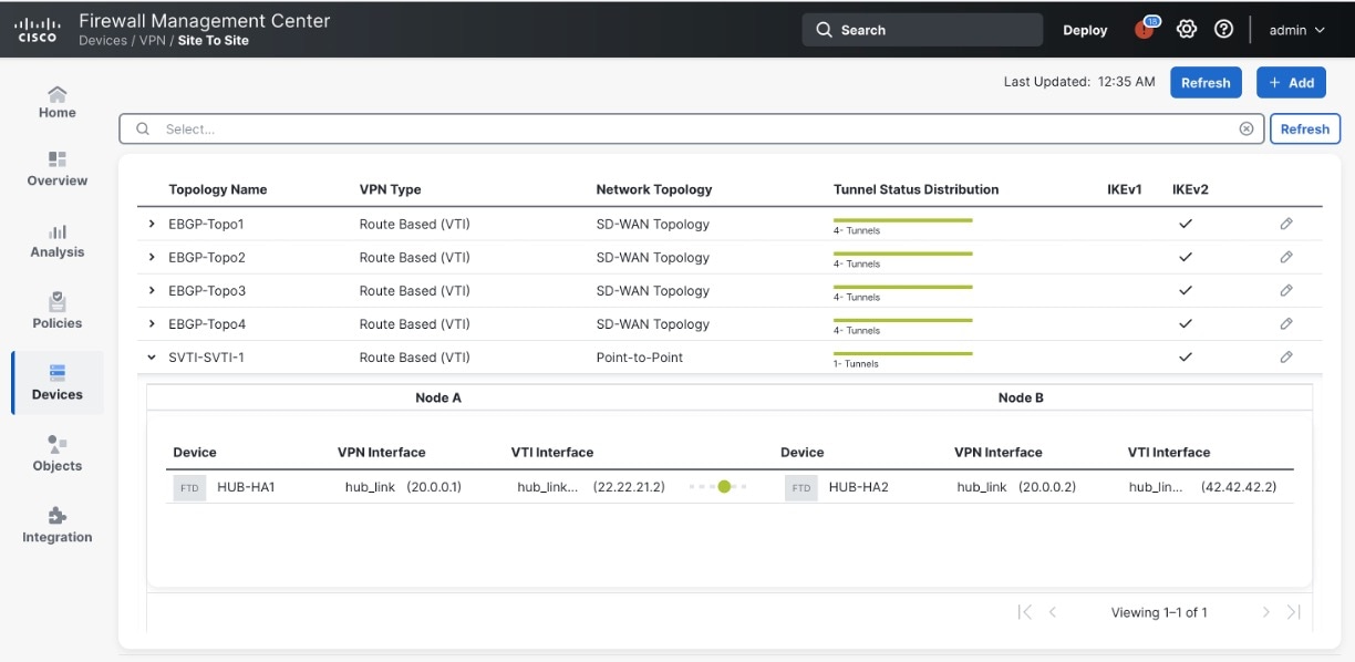
) icon. A pane with tunnel details and more actions appears.

  3. Click the CLI Details tab in the side pane to view the show commands and details of the IPsec security associations.

View Virtual Tunnel Interfaces of the Devices

To view the dynamic VTIs of hubs and static VTIs of spokes:

  1. Choose Devices > Device Management.

  2. Click the edit icon for a hub or a spoke device.

  3. Click the Interface tab.

  4. Click the Virtual Tunnels tab.

    For each VTI, you can view details such as name, IP address, IPsec mode, tunnel source interface details, topology, and remote peer IP.

Following image shows an example of the virtual access interfaces created dynamically by a hub's DVTI:

Following image shows an example of the static tunnel virtual interfaces (SVTIs) created on a spoke by the SD-WAN wizard:

The SD-WAN wizard assigns IP addresses to these tunnel interfaces from the IP address pool of the hub.

Verify Routing on the Hub and Branches

To verify the BGP configuration of the hubs and spokes of the SD-WAN topologies:

  1. Choose Devices > Device Management.

  2. Click the edit icon for a hub or a spoke device.

  3. Click the Device tab.

  4. Click CLI in the General card. The CLI Troubleshoot window appears.

  5. Enter the following commands in the Command field and click Execute:

    • show route

    • show bgp summary

Use Cases for SD-WAN Capabilities

Use the Cisco Secure Firewall Threat Defense SD-WAN Design and Deployment Guide to design and deploy SD-WAN architectures using Firewall Threat Defense and Firewall Management Center. This guide explains design principles, configuration workflows, and best practices.

Use these guides for detailed instructions for the primary use cases leveraging the SD-WAN capabilities supported by Cisco Secure Firewall.

Monitoring SD-WAN Topologies

SD-WAN Summary Dashboard

The SD-WAN Summary dashboard (Insights & Reports > VPN dashboards > SD-WAN Summary) provides a snapshot of your WAN devices and their interfaces. This dashboard helps you to:

  • Identify issues with the underlay and overlay (VPN) topologies.

  • Troubleshoot VPN issues using the existing Health Monitoring, Device Management, and Site-to-Site Monitoring pages.

  • Monitor application performance metrics of WAN interfaces. The threat defense steers application traffic based on these metrics.

A WAN device must meet one of the following criteria:

  • The device must be a VPN peer.

  • The device must have WAN interface.

A WAN interface must meet one of the following criteria:

  • The interface has IP address-based path monitoring enabled on it.

  • The interface has a Policy Based Routing (PBR) policy with at least one application configured to monitor it.

For more information about PBR policy and path monitoring, see Policy Based Routing.

Click Uplink Decisions to view the VPN Troubleshooting page. You can view syslogs with ID: 880001. These syslogs show the threat defense interfaces through which it steers traffic based on the configured PBR policy.

To view the above syslogs and to view the data on this dashboard, ensure that you review Prerequisites for Using SD-WAN Summary Dashboard.

For clusters, this dashboard displays application performance metrics of only the control node and not the data nodes.

Prerequisites for Using SD-WAN Summary Dashboard

  • You must be an Admin, Security Analyst, or Maintenance user to view this dashboard.

  • Threat defense devices must be Version 7.2 or later.

  • Enable IP-based path monitoring and HTTP-based application monitoring on the WAN interfaces.

    1. Choose Devices > Device Management.

    2. Click the edit icon adjacent to the device that you want to edit.

    3. Click the edit icon adjacent to the interface that you want to edit.

    4. Click the Path Monitoring tab.

    5. Check the Enable IP based Monitoring check box.

    6. Check the Enable HTTP based Application Monitoring check box.

    7. Click OK.

  • Configure a PBR policy with at least one application configured to monitor it:

    1. Choose Devices > Device Management.

    2. Click the edit icon adjacent to the device that you want to edit.

    3. Click Routing.

    4. In the left pane, click Policy Based Routing.

    5. Click Add.

    6. From the Ingress Interface drop-down list, choose an interface.

    7. Click Add to configure a forwarding action.

    8. Configure the parameters.

    9. Click Save.

  • To view the application performance metrics for the WAN interfaces, you must:

    • Threat defense devices must be Version 7.4.1.

    • Enable data collection from the SD-WAN module in the health policy.

      1. Choose Troubleshooting > + Show more > Health > Policies.

      2. Click the Edit health policy icon.

      3. In the Health Modules tab, under SD-WAN, click the SD-WAN Monitoring toggle button.

    • Configure applications for the PBR policies.

      1. Choose Objects > Access List > Extended.

      2. Click the edit icon adjacent to the access list and add the applications for the PBR policy.

    • Configure the forwarding action for the policy with one of the four application metrics.

      1. Choose Devices > Device Management.

      2. Click the edit icon adjacent to the device that you want to edit.

      3. Click Routing.

      4. In the left pane, click Policy Based Routing.

      5. Click the edit icon adjacent to the policy that you want to edit.

      6. In the Edit Policy Based Route dialog box, click the edit icon adjacent to the corresponding ACL.

      7. In the Edit Forwarding Actions dialog box, from the Interface Ordering drop-down list, choose one of the following options:

        • Minimal Jitter

        • Maximum Mean Opinion Score

        • Minimal Round-Trip Time

        • Minimal Packet Loss

        If you choose Interface Priority or Order, application monitoring is not enabled on the interface.

    • Configure ECMP on the WAN interfaces:

      1. Choose Devices > Device Management.

      2. Click the edit icon adjacent to the device that you want to edit.

      3. Click Routing.

      4. In the left pane, click ECMP.

      5. Click Add and specify a name for the ECMP zone.

      6. Click Add to move interfaces from Available Interfaces to Selected Interfaces.

      7. Click OK.

    • Ensure that traffic passes through the interface.

    • Enable DNS inspection on each WAN device so that the threat defense device can do DNS snooping, and configure the trusted DNS servers:

      1. Choose Devices > Platform Settings.

      2. Click the edit icon adjacent to the threat defense policy that you want to edit.

      3. In the left pane, click DNS.

      4. Click the DNS Settings tab.

      5. Check the Enable DNS name resolution by device check box.

      6. Click the Trusted DNS Servers tab.

      7. Do one of the following:

        • Click the Trust Any DNS server toggle button.

        • Under Specify DNS Servers, click Edit to add trusted DNS servers.

  • To view syslogs when you click Uplink Decisions, you must:

    • Choose Devices > Platform Settings and create or edit a threat defense policy.

    • In the left pane, click Syslog.

    • Click the Logging Setup tab.

    • Check the Enable Logging check box to turn on the data plane system logging for the threat defense device.

    • Click the All Logs radio button to enable logging of all the troubleshooting syslog messages.

      or

      Click the VPN Logs radio button to enable logging of only the VPN troubleshooting messages.

    • Click Save.

Monitor WAN Devices and Interfaces Using the SD-WAN Summary Dashboard

The SD-WAN Summary dashboard has the following widgets under the Overview tab:

Top Applications

This widget displays the top 10 applications ranked according to throughput.

You can choose a time range for the widget data from the Show Last drop-down list. The range is 15 minutes to two weeks.

WAN Connectivity

This widget provides a summary of the WAN interfaces statuses. It shows the number of WAN interfaces that are in the Online, Offline or No Data states. Note that you cannot monitor subinterfaces using this widget.

Click View All Interfaces to view more details about the interfaces in the health monitor page.

If a WAN interface is in the Offline or No Data state, you can troubleshoot it from the health monitor page:

  1. In the Monitoring pane, expand Devices.

  2. Click the corresponding WAN device to view the device-specific health details.

  3. Click the Interface tab to view the interface status and aggregate traffic statistics for a specific time.

    Alternatively, you can click View System & Troubleshoot Details. The health monitor page is displayed with all the necessary details.

VPN Topology

This widget provides a summary of the site-to-site VPN tunnel statuses. It shows the number of Active, Inactive, and No Active Data VPN tunnels.

Click View All Connections to view the VPN tunnel details in the Site-to-site VPN Monitoring dashboard.

If the tunnels are in the Inactive or No Active Data state, you can troubleshoot using the Site-to-site VPN Monitoring dashboard. In the Tunnel Status widget, hover your cursor over a topology, click View (View button) and do one of the following:

  • Click the CLI Details tab to view the details of the VPN tunnels.

  • Click the Packet Tracer tab to use the packet tracer tool for the topology.

WAN Interface Throughput

This widget monitors the average throughput of the WAN interfaces during the chosen time period.

The interface throughput is classified into four bands. These details aid in cost planning and resourcing. You can choose a time range for the widget data from the Show Last drop-down list. The range is from 15 minutes to two weeks.

Click View Health Monitoring to view more details about the interface in the health monitor page.

Device Inventory

This widget lists all the managed WAN devices and groups them according to the model.

Click View Device Management to view more details about the device in the Device Management page.

WAN Device Health

This widget displays the device count according to the health of the WAN devices. You can view the number of devices with errors, warnings, or those that are in Disabled state.

Click View Health Monitoring to view the alarms, and quickly identify, isolate, and resolve issues.

If the health of a device is affected, you can troubleshoot it from the health monitor page.

  1. In the Monitoring pane, expand Devices.

  2. Click the corresponding WAN device to view the device-specific health details.

  3. Click View System & Troubleshoot Details. The health monitor page is displayed with all the necessary details.

A device can be in Disabled state for multiple reasons, including the following:

  • Management interface is disabled.

  • Device is powered off.

  • Device is being upgraded.

Monitor Application Performance Metrics of WAN Interfaces Using the SD-WAN Summary Dashboard

Under the Application Monitoring tab, you can select a WAN device and view the application performance metrics for the corresponding WAN interfaces. These metrics include Jitter, Round Trip Time (RTT), Mean Opinion Score (MOS), and Packet Loss.

By default, the metrics data is refreshed every 5 minutes. You can change the refresh time; the range is from 5 to 30 minutes. You can view the metrics in tabular and graphical formats. For each WAN interface, the latest metric value appears in the table. For graphical data, you can choose a time interval of up to 24 hours to view the metrics data for the corresponding WAN interfaces.