About policy-based routing
Policy-based routing characteristics
In traditional routing, packets are routed based on the destination IP address. Changing the routing of specific traffic in a destination-based routing system is difficult. PBR extends and complements the mechanisms provided by routing protocols.
PBR allows you to set the IP precedence. It also allows you to specify a path for certain traffic, such as priority traffic over a high-cost link. With PBR, you can define routing that is based on criteria other than destination network such as source port, destination address, destination port, protocol, applications, or a combination of these objects.
You can use PBR to classify the network traffic based on applications, username, group membership, and security group association. This routing method applies to scenarios involving numerous devices accessing applications and data in large network deployment. In large deployments, network traffic is typically backhauled to a hub as encrypted traffic in a route-based VPN. These topologies often result in issues such as packet latency, reduced bandwidth, and packet drop. Resolving these issues requires costly, complex deployments and management.
PBR policy enables you to securely break out traffic for specified applications. You can configure PBR policy in the Secure Firewall Management Center user interface to allow the applications to be directly accessed.
Consider a company that has two links between locations: one a high-bandwidth, low-delay expensive link, and the other a low-bandwidth, higher-delay, less-expensive link. While using traditional routing protocols, the higher-bandwidth link gets most, if not all, of the traffic sent across it based on the metric savings obtained by the bandwidth, delay, or both (using EIGRP or OSPF) characteristics of the link. With PBR, you can route higher priority traffic over the high-bandwidth/low-delay link, while sending all other traffic over the low-bandwidth/high-delay link.
These scenarios demonstrate policy-based routing applications:
-
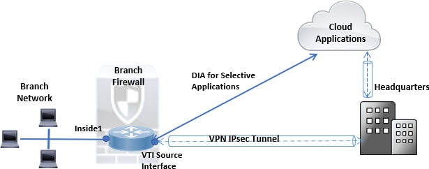
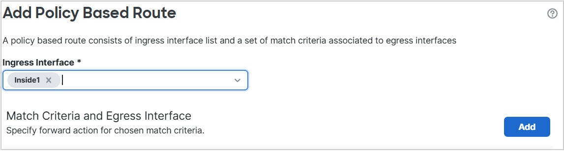
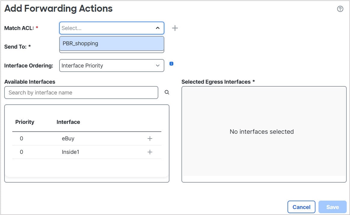
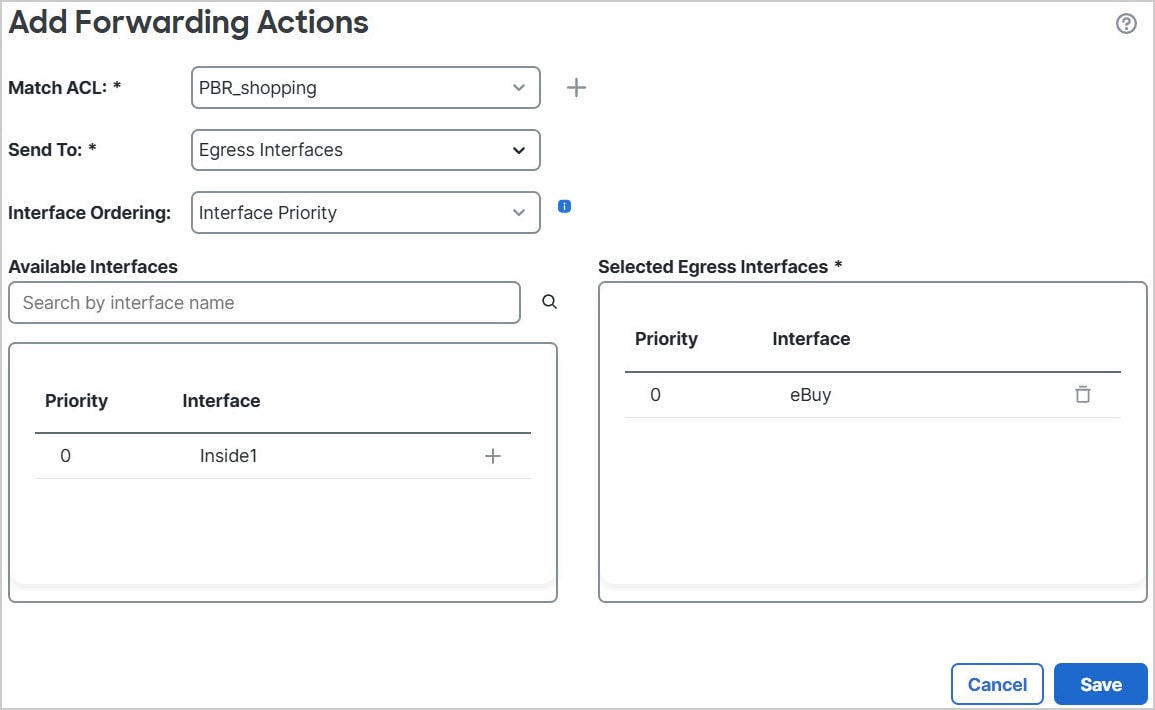
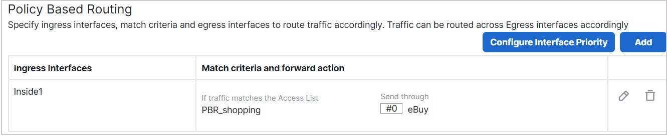
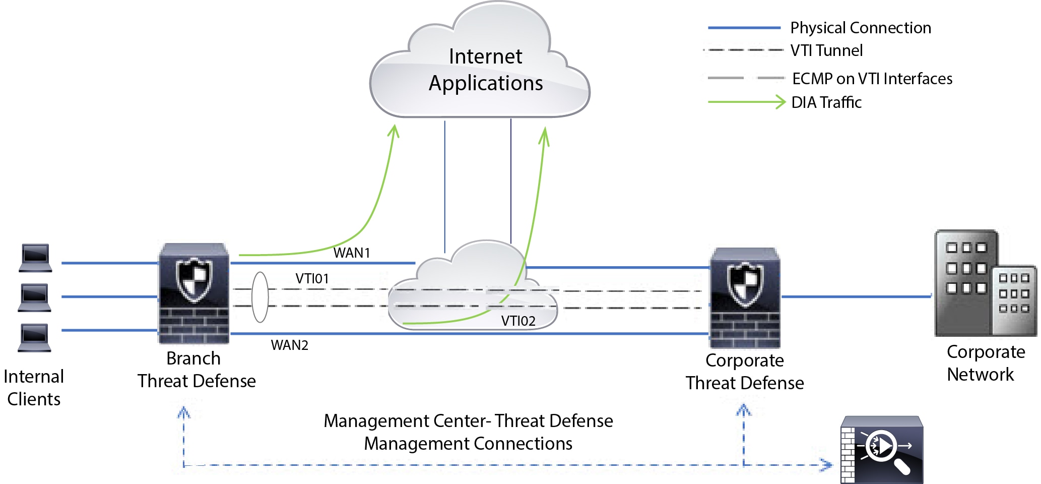
Direct internet access: In this topology, application traffic from the branch office can be routed directly to the internet instead of through the VPN tunnel connecting to the headquarters. The branch Firewall Threat Defense is configured with an internet exit point. The PBR policy is applied on the ingress interface (Inside 1) to identify the traffic based on the applications, user identity (username and group membership), and Security Group Tag (security group association) defined in the ACL. Correspondingly, the traffic is forwarded through the egress interfaces directly to the internet or to the IPsec VPN tunnel.
-
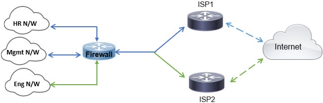
Equal-access and source-sensitive routing: In this topology, traffic from the HR and Mgmt networks can be configured to go through ISP1 and traffic from Eng network can be configured to go through ISP2. Thus, policy-based routing enables the network administrators to provide equal-access and source-sensitive routing, in this example.
-
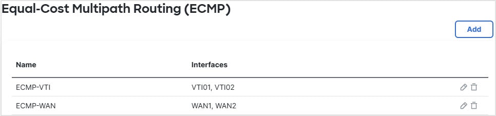
Load sharing: In addition to the dynamic load-sharing capabilities offered by ECMP load balancing, network administrators can now implement policies to distribute traffic among multiple paths based on the traffic characteristics. As an example, in the topology depicted in the Equal-Access Source Sensitive Routing scenario, an administrator can configure policy-based routing to route the traffic from HR network through ISP1 and traffic from Eng network through ISP2 and thus share the load.


 Feedback