
About clustering: private cloud
This section describes the clustering architecture and how it works.
How the cluster fits into your network
The cluster consists of multiple firewalls acting as a single device. To act as a cluster, the firewalls need the following infrastructure:
-
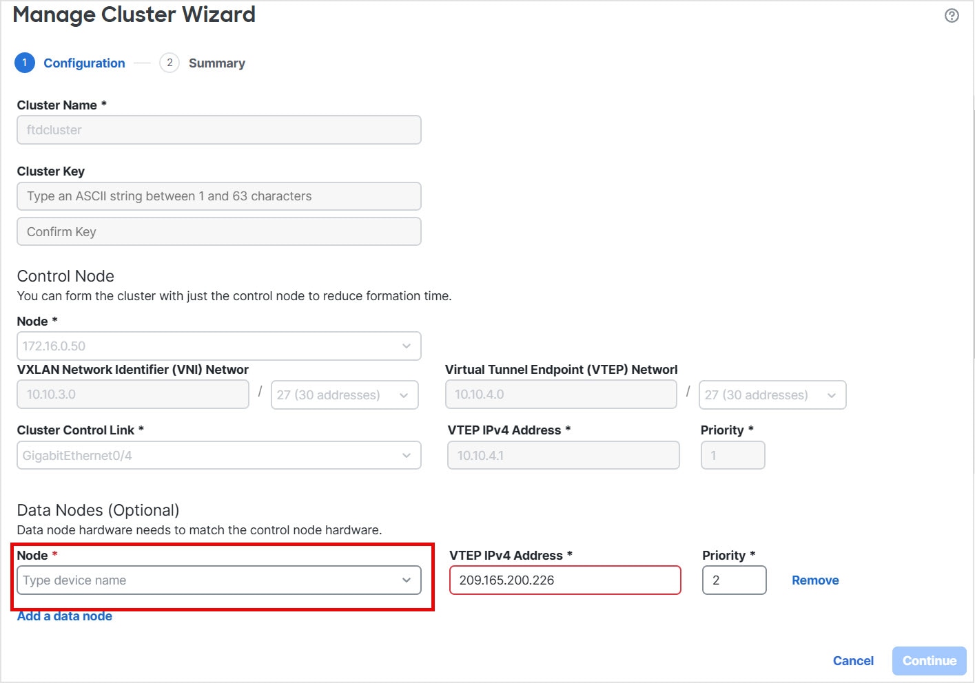
Isolated network for intra-cluster communication, known as the cluster control link, using VXLAN interfaces. VXLANs, which act as Layer 2 virtual networks over Layer 3 physical networks, let the Firewall Threat Defense Virtual send broadcast/multicast messages over the cluster control link.
-
Management access to each firewall for configuration and monitoring. The Firewall Threat Defense Virtual deployment includes a Management 0/0 interface that you will use to manage the cluster nodes.
When you place the cluster in your network, the upstream and downstream routers need to be able to load-balance the data coming to and from the cluster using Layer 3 Individual interfaces and one of the following methods:
-
Policy-Based Routing—The upstream and downstream routers perform load balancing between nodes using route maps and ACLs.
-
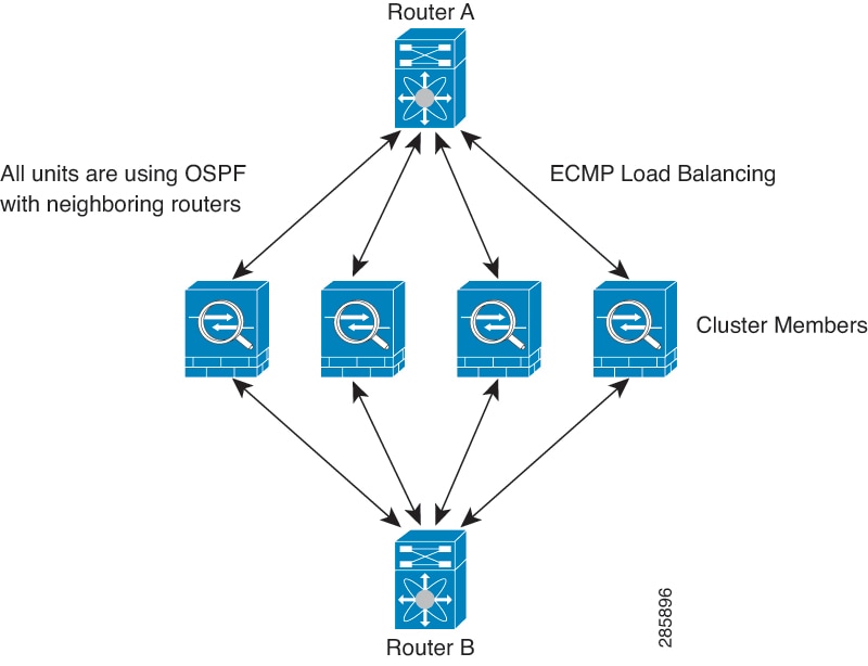
Equal-Cost Multi-Path Routing—The upstream and downstream routers perform load balancing between nodes using equal cost static or dynamic routes.
Layer 2 Spanned EtherChannels are not supported.
Control and data node roles
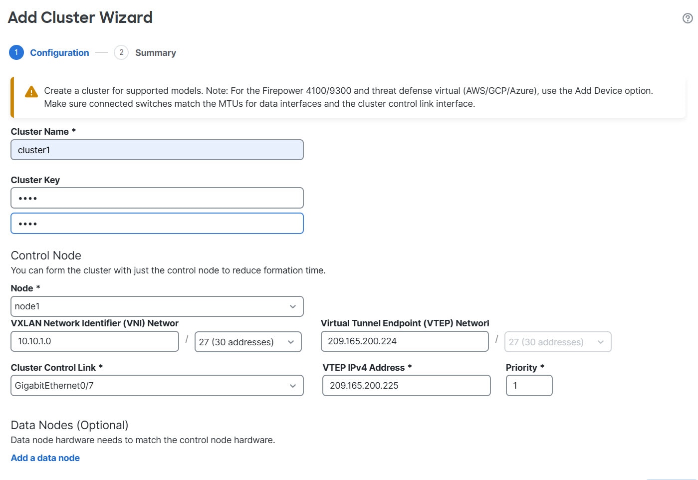
When you add a cluster in the Firewall Management Center , you choose one firewall to be the control node, and all additional firewalls to be data nodes. When you first create the cluster, the control node you specify will become the control node simply because it is the first node added to the cluster. Later, if multiple cluster nodes come online at the same time, the control node is determined by the priority setting; the priority is set between 1 and 100, where 1 is the highest priority.
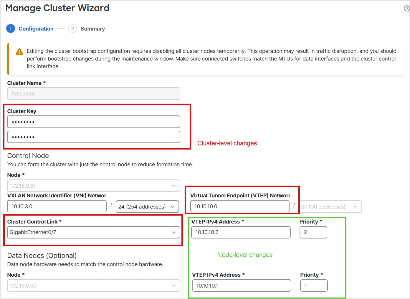
When you create the cluster and deploy the cluster configuration, the Firewall Management Center deploys a special bootstrap configuration to each node that includes fundamental settings such as the cluster control link configuration. The bootstrap configuration lets each node join the cluster. Most bootstrap settings are defined in the cluster wizard; however, you define the cluster control link interface hardware configuration (for example, creating an EtherChannel or setting the Ethernet speed) on the control node before you create the cluster. The cluster control link settings are copied to the bootstrap configuration for each node.
All nodes in the cluster share the same policy configuration. The node that you initially specify as the control node will overwrite the configuration on the data nodes when they join the cluster, so you only need to perform initial configuration on the control node before you form the cluster. After you create the cluster, all configuration changes are made at the cluster level and are shared by all nodes.
Some features do not scale in a cluster, and the control node handles all traffic for those features.
Individual interfaces
You can configure cluster interfaces as individual interfaces.
Individual interfaces are normal routed interfaces, each with their own local IP address used for routing. The main cluster IP address for each interface is a fixed address that always belongs to the control node. When the control node changes, the main cluster IP address moves to the new control node, so management of the cluster continues seamlessly.
IPS-only interfaces (inline sets and passive interfaces) are not supported as Individual interfaces.
Because interface configuration must be done only on the control node, configure a pool of IP addresses for a given interface on the cluster nodes, including one for the control node.
Load balancing must be configured separately on the upstream switch.
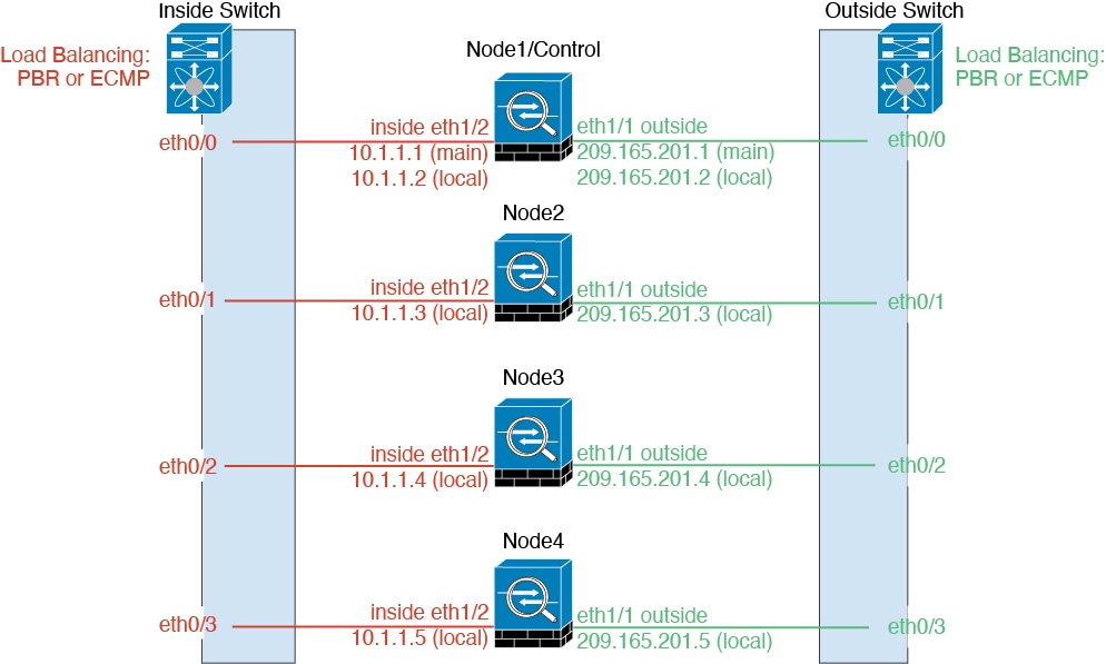
Layer 2 Spanned EtherChannels are not supported.
Policy-based routing
When using individual interfaces, each Firewall Threat Defense interface maintains its own IP address and MAC address. One method of load balancing is Policy-Based Routing (PBR).
We recommend this method if you are already using PBR, and want to take advantage of your existing infrastructure.
PBR makes routing decisions based on a route map and ACL. You must manually divide traffic between all Firewall Threat Defenses in a cluster. Because PBR is static, it may not achieve the optimum load balancing result at all times. To achieve the best performance, we recommend that you configure the PBR policy so that forward and return packets of a connection are directed to the same Firewall Threat Defense.
For example, if you have a Cisco router, redundancy can be achieved by using Cisco IOS PBR with Object Tracking. Cisco IOS Object Tracking monitors each Firewall Threat Defense using ICMP ping. PBR can then enable or disable route maps based on reachability of a particular Firewall Threat Defense.
Equal-cost multi-path routing
When using Individual interfaces, each Firewall Threat Defense interface maintains its own IP address and MAC address. One method of load balancing is Equal-Cost Multi-Path (ECMP) routing.
We recommend this method if you are already using ECMP, and want to take advantage of your existing infrastructure.
ECMP routing considerations
ECMP routing can forward packets over multiple best paths that tie for top place in the routing metric. Like EtherChannel, a hash of source and destination IP addresses and/or source and destination ports can be used to send a packet to one of the next hops.
If you use static routes for ECMP routing, then the Firewall Threat Defense failure can cause problems; the route continues to be used, and traffic to the failed Firewall Threat Defense will be lost.
If you use static routes, be sure to use a static route monitoring feature such as Object Tracking. We recommend using dynamic routing protocols to add and remove routes, in which case, you must configure each Firewall Threat Defense to participate in dynamic routing.
Cluster Control Link
Each node must dedicate one interface as a VXLAN (VTEP) interface for the cluster control link. For more information about VXLAN, see Configure VXLAN interfaces .
VXLAN Tunnel Endpoint
VXLAN tunnel endpoint (VTEP) devices perform VXLAN encapsulation and decapsulation. Each VTEP has two interface types: one or more virtual interfaces called VXLAN Network Identifier (VNI) interfaces, and a regular interface called the VTEP source interface that tunnels the VNI interfaces between VTEPs. The VTEP source interface is attached to the transport IP network for VTEP-to-VTEP communication.
VTEP Source Interface
The VTEP source interface is a regular Firewall Threat Defense Virtual interface with which you plan to associate the VNI interface. You can configure one VTEP source interface to act as the cluster control link. The source interface is reserved for cluster control link use only. Each VTEP source interface has an IP address on the same subnet. This subnet should be isolated from all other traffic, and should include only the cluster control link interfaces.
VNI Interface
A VNI interface is similar to a VLAN interface. It is a virtual interface that keeps network traffic separated on a given physical interface by using tagging. You can only configure one VNI interface. Each VNI interface has an IP address on the same subnet.
Peer VTEPs
Unlike regular VXLAN for data interfaces, which allows a single VTEP peer, Firewall Threat Defense Virtual clustering allows you to configure multiple peers.
Cluster control link traffic overview
Cluster control link traffic includes both control and data traffic.
Control traffic includes:
-
Control node election.
-
Configuration replication.
-
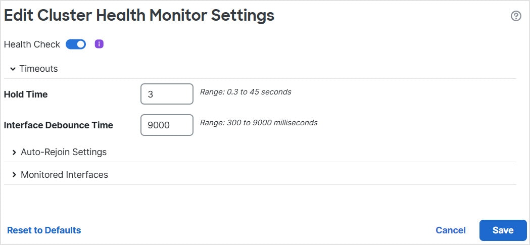
Health monitoring.
Data traffic includes:
-
State replication.
-
Connection ownership queries and data packet forwarding.
Configuration replication
All nodes in the cluster share a single configuration. You can only make configuration changes on the control node (with the exception of the bootstrap configuration), and changes are automatically synced to all other nodes in the cluster.
Management network
You must manage each node using the Management interface. Management from a data interface is not supported with clustering.







 Feedback