Edit General Settings
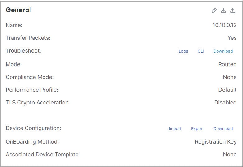
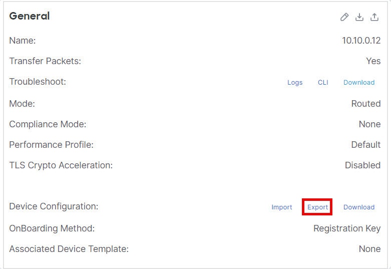
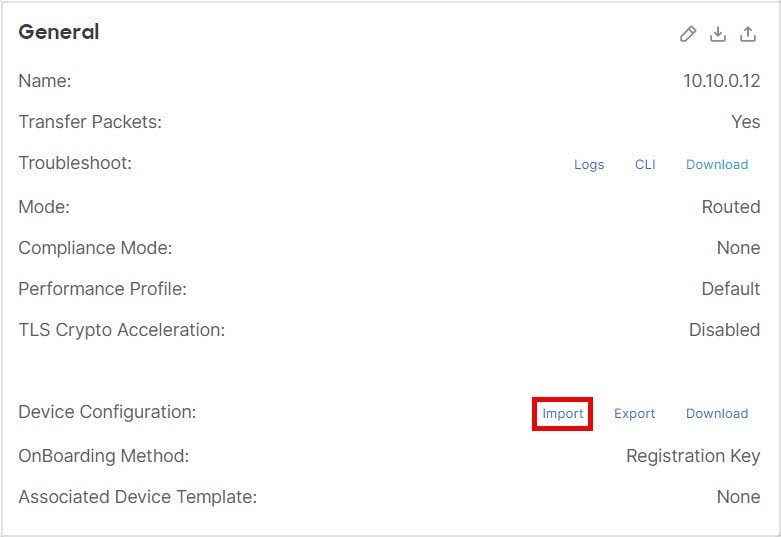
The General section of the Device page displays the settings described in the table below.
|
Field |
Description |
|---|---|
|
Name |
The display name of the device on the Firewall Management Center. |
|
Transfer Packets |
This displays whether or not the managed device sends packet data with the events to the Firewall Management Center. |
|
Troubleshoot |
Lets you generate and download troubleshooting files and also see CLI command output. See Generate Troubleshooting Files and View CLI Output. |
|
Mode |
The displays the mode of the management interface for the device: routed or transparent. |
|
Compliance Mode |
This displays the security certifications compliance for a device. Valid values are CC, UCAPL and None. |
|
Performance Profile |
This displays the core allocation performance profile for the device, as configured in the platform settings policy. |
|
TLS Crypto Acceleration: |
Shows whether TLS crypto acceleration is enabled or disabled. |
|
Device Configuration |
Lets you copy, export, or import a configuration. See Copy a Configuration to Another Device and Export and Import the Device Configuration. |
|
OnBoarding Method |
Shows whether the device was registered using a registration key or using the serial number (zero-touch provisioning). |
Procedure
|
Step 1 |
Choose . |
|
Step 2 |
Next to the device you want to modify, click Edit ( |
|
Step 3 |
Click Device. |
|
Step 4 |
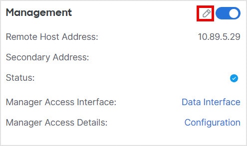
In the General section, click Edit ( |
|
Step 5 |
For Troubleshoot actions, see Generate Troubleshooting Files and View CLI Output. |
|
Step 6 |
For Device Configuration actions, see Copy a Configuration to Another Device and Export and Import the Device Configuration. |
|
Step 7 |
Click Deploy. |
What to do next
-
Deploy configuration changes; see Deploy configuration changes.
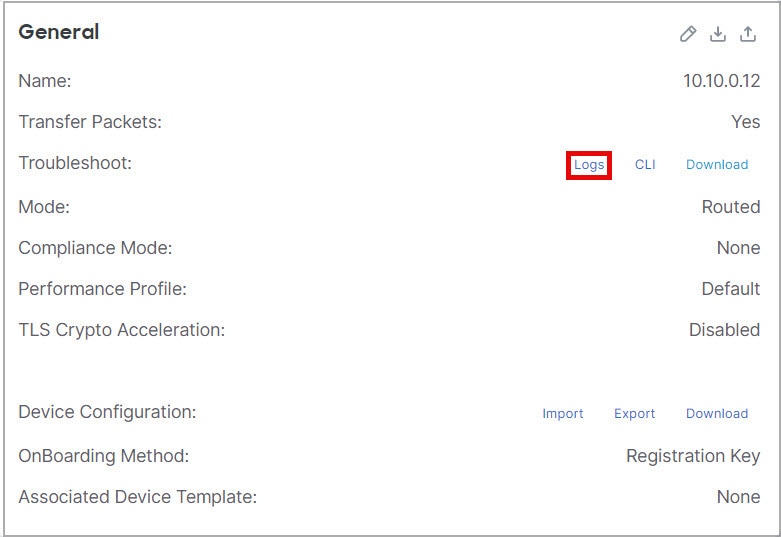
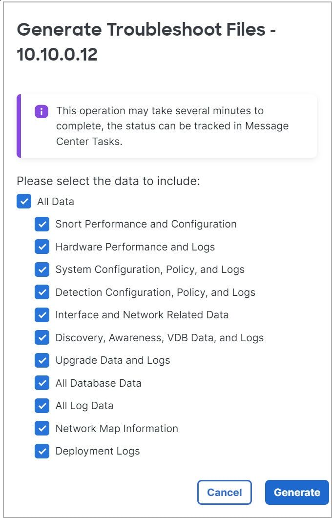
Generate Troubleshooting Files
You can generate and download troubleshooting files for each device and also for all cluster nodes. For a cluster, you can download all files as a single compressed file. You can also include cluster logs for the cluster for cluster nodes.
You can alternatively trigger file generation from the , from the More ( ) drop-down list, choose Troubleshoot Files.
Procedure
|
Step 1 |
Choose . |
|
Step 2 |
Next to the device or cluster you want to view, click Edit ( In a multidomain deployment, if you are not in a leaf domain, the system prompts you to switch. |
|
Step 3 |
Click Device or Cluster. |
|
Step 4 |
Generate logs for the device or for all cluster nodes.
|
|
Step 5 |
To download the generated logs, in the General area, Troubleshoot section, click Download. 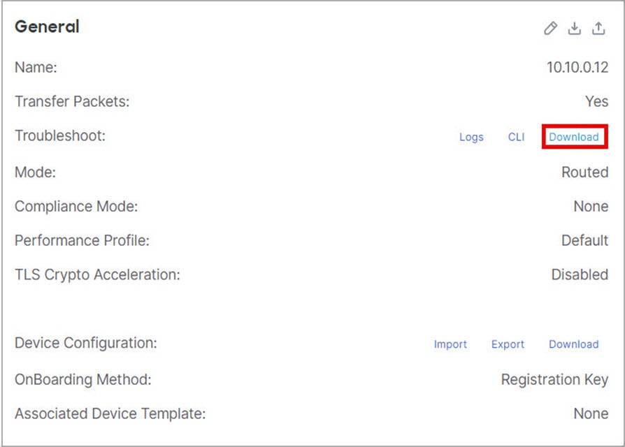
The logs are downloaded to your computer. |
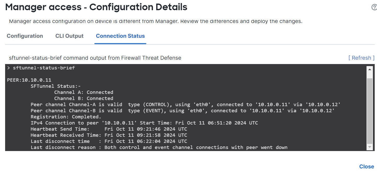
View CLI Output
You can view a set of pre-defined CLI outputs that can help you troubleshoot the device or cluster. You can also enter any show command and see the output.
For a device, the following commands are executed:
-
show version
-
show asp drop
-
show counters
-
show int ip brief
-
show blocks
-
show cpu detailed
For a cluster or cluster node:
-
show running-config cluster
-
show cluster info
-
show cluster info health
-
show cluster info transport cp
-
show version
-
show asp drop
-
show counters
-
show arp
-
show int ip brief
-
show blocks
-
show cpu detailed
-
show interface ccl_interface
-
ping ccl_ip size ccl_mtu repeat 2
Procedure
|
Step 1 |
Choose . |
|
Step 2 |
Next to the device or cluster you want to view, click Edit ( In a multidomain deployment, if you are not in a leaf domain, the system prompts you to switch. |
|
Step 3 |
Click Device or Cluster. |
|
Step 4 |
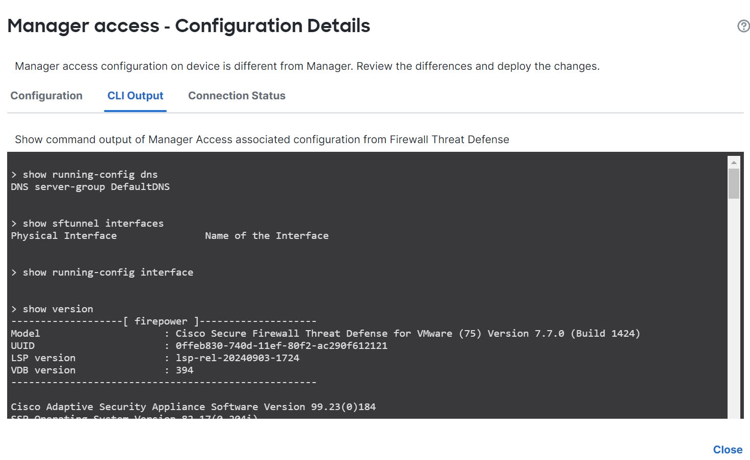
In the General area, Troubleshoot section, click CLI. 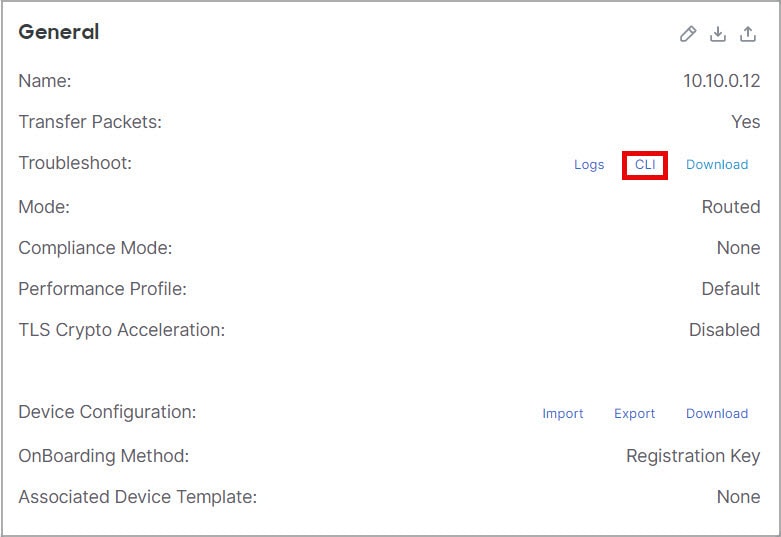
The CLI Troubleshoot dialog box appears with the pre-defined CLIs executed. 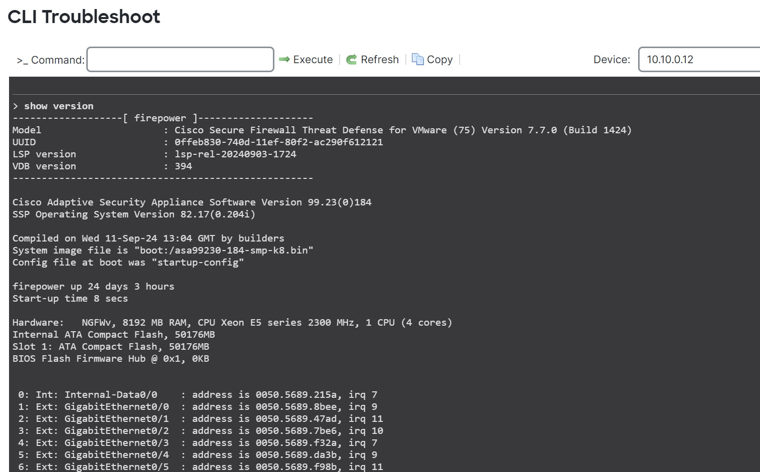
|
|
Step 5 |
On the CLI Troubleshoot dialog box, you can perform the following tasks.
|
|
Step 6 |
Click Close. |
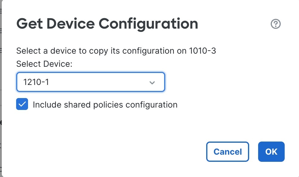
Copy a Configuration to Another Device
Before you begin
Confirm that:
-
The source and destination devices are the same model and are running the same version of the software.
-
The source is either a standalone device or a high availability pair.
-
The destination device is a standalone device.
-
The source and destination devices have the same number of physical interfaces.
-
The source and destination devices are in the same firewall mode: routed or transparent.
-
The source and destination devices are in the same security-certifications-compliance mode.
-
The source and destination devices are in the same domain.
-
Configuration deployment is not in progress on either the source or the destination devices.
Procedure
|
Step 1 |
Choose . |
|
Step 2 |
Next to the device you want to modify, click Edit ( |
|
Step 3 |
Click Device. |
|
Step 4 |
In the General section, do one of the following: 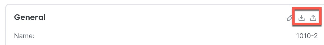
|
|
Step 5 |
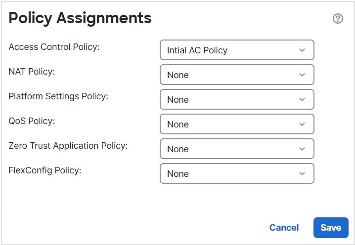
(Optional) Check Include shared policies configuration check box to copy policies. Shared policies like AC policy, NAT, Platform Settings and FlexConfig policies can be shared across multiple devices. |
|
Step 6 |
Click OK. You can monitor the status of the copy device configuration task on Tasks in the Message Center. |


 Warning |
When you have completed the copy device configuration task, you cannot revert the target device to its original configuration. |
Export and Import the Device Configuration
 Note |
|
You can export all of the the device-specific configuration configurable on the Device pages, including:
-
Interfaces
-
Inline Sets
-
Routing
-
DHCP
-
VTEP
-
Associated objects
You can then import the saved configuration for the same device in the following use cases:
-
Moving the device to a different Firewall Management Center—First unregister the device from the original Firewall Management Center, then add the device to the new Firewall Management Center. Then you can import the saved configuration.
-
Moving the device between domains—When you move a device between domains, some device-specific configuration is not retained because supporting objects (such as interface groups for security zones) do not exist in the new domain. By importing the configuration after the domain move, any necessary objects are created for that domain, and the device configuration is restored.
-
Restore an old configuration—If you deployed changes that negatively impacted the operation of the device, you can import a backup copy of a known working configuration to restore a previous operational state.
-
Reregistering a device—If you unregister a device from the Firewall Management Center, but then want to add it back, you can import the saved configuration.
See the following guidelines:
-
You can only import the configuration to the same device (the UUID must match). You cannot import a configuration to a different device, even if it is the same model.
-
Do not change the version running on the device between exporting and importing; the version must match.
-
If you make inventory changes after your export (such as adding or deleting network modules or configuring or joining breakout ports), the device inventory will not match the Firewall Management Center. In this case, the device inventory will be maintained, and you will be prompted to sync the interfaces (see Sync Interface Changes with the Firewall Management Center) and discard incompatible configuration in the Firewall Management Center when you try to deploy. You will have to repeat the inventory changes and related configuration in the Firewall Management Center.
-
If you export a standalone configuration, you cannot import it to a high availability pair or vice versa.
-
When moving the device to a different Firewall Management Center, the target Firewall Management Center version must be the same as the source version.
-
If an object doesn't exist, it will be created. If an object exists, but the value is different, see below:
Table 2. Object Import Action Scenario
Import Action
Object exists with the same name and value.
Reuse existing objects.
Object exists with the same name but different value.
Network and Port objects: Create object overrides for this device. See Object overrides.
Interface objects: Create new objects. For example, if both the type (security zone or interface group) and the interface type (routed or switched, for example) do not match, then a new object is created.
All other objects: Reuse existing objects even though the values are different.
Object doesn't exist.
Create new objects.
Procedure
|
Step 1 |
Choose . |
|
Step 2 |
Next to the device you want to edit, click Edit ( |
|
Step 3 |
Click Device. |
|
Step 4 |
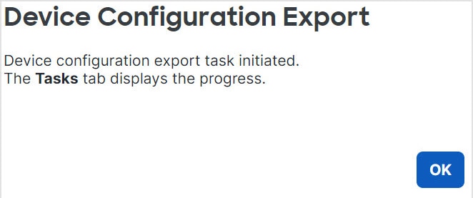
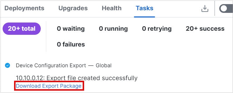
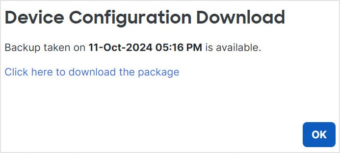
Export the configuration.
|
|
Step 5 |
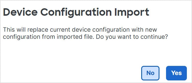
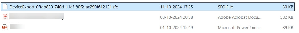
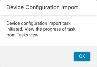
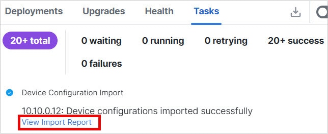
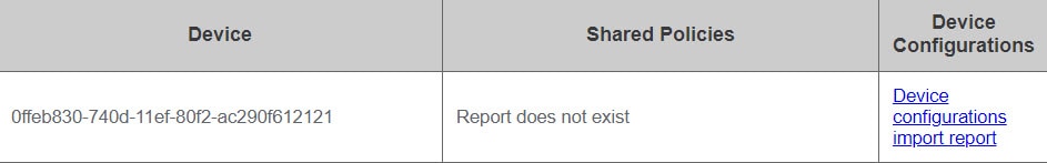
Import the configuration.
|


 Feedback