Set Up SD-WAN Branch Office with Dual ISPs Using Registration Key and Device Templates

In this chapter, we show you how to set up your SD-WAN branch office with dual ISPs using device registration keys and device templates. The use case details the scenario, network topology, best practices, and prerequisites. It also provides a comprehensive end-to-end procedure for seamless implementation.

Overview of SD-WAN Wizard and Device Templates

Onboarding multiple devices on a branch network and establishing a secure network infrastructure that connects these branches to the central headquarters is challenging. Manually configuring and deploying these devices within an SD-WAN topology is time-intensive and error-prone, potentially leading to inconsistencies in network settings and security vulnerabilities across different locations.

You can mitigate these issues by using the Cisco Secure Firewall Management Center (subsequently referred to as management center) and Cisco Secure Firewall Threat Defense (subsequently referred to as threat defense devices) devices. The Secure Firewall solution streamlines the deployment of secure branch networks with the new SD-WAN VPN wizard and device templates, which are available in management center Version 7.6.

The SD-WAN VPN wizard simplifies the configuration of VPN tunnels between your centralized headquarters and remote branch sites. It automates the VPN and routing setup for your SD-WAN overlay network.

Device templates facilitate the deployment of multiple branch devices with preprovisioned initial configurations. Using these templates, you can easily configure SD-WAN VPN connections and seamlessly add spokes to your SD-WAN topologies.
Is this Guide for You?

This guide is designed for network administrators responsible for onboarding branch office devices using their registration keys with the Management Center. It provides detailed instructions for deploying these devices with pre-provisioned configurations in a dual ISP SD-WAN topology. Note that this deployment does not support Threat Defense Virtual.

Sample Scenario

Alex, a network administrator for an enterprise with multiple branch offices across various cities, wants to onboard several devices to a branch network with preconfigured settings and establish a secure network infrastructure that connects these branches to the central headquarters. Alex decides to use the new SD-WAN wizard and device templates in the management center. These new features streamline the process by providing centralized control, ensuring uniform configurations, and enabling efficient provisioning and scalability across the corporate network.

System Requirements

The following table displays the platforms and versions for this use case.

Product

Version

Version Used in This Document

Cisco Secure Firewall Management Center (formerly Firepower Management Center [FMC])

7.6 and later

7.6

Cisco Secure Firewall Threat Defense (formerly Firepower Threat Defense [FTD])

7.4.1 and later of the following models:

  • Firepower 1000 Series

  • Firepower 2100 Series

  • Secure Firewall 3100 Series

  • Secure Firewall 1200 Series

Firepower 1120 Version 7.6

Network Topology Depicting Dual ISP with Hubs and Spokes in the Same Region

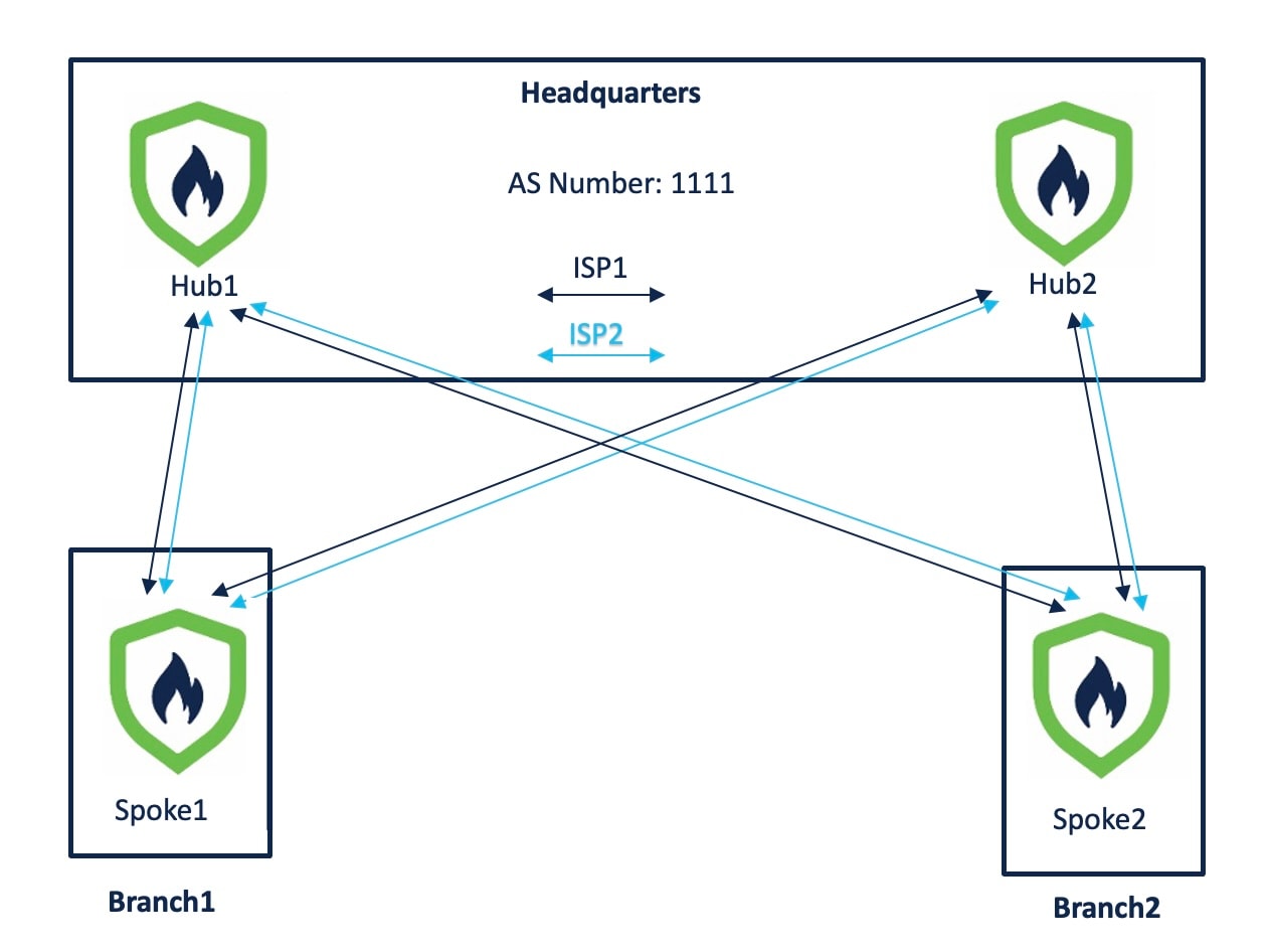
In the following sample dual ISP topology, the hubs and spokes are in a single region, with autonomous system (AS) number as 1111. The hubs and spokes use Internal Border Gateway Protocol (iBGP) as the routing protocol to exchange routing information.

  • Hub1 and Hub2 are Threat Defense hub devices at the headquarters.

  • Spoke1 and Spoke2 are Threat Defense spoke devices at the branches.

  • outside-isp1 is the VPN interface of each spoke to ISP1.

  • outside-isp2 is the VPN interface of each spoke to ISP2.

Alex aims to onboard a Cisco Firepower 1120 Threat Defense device into an existing dual ISP SD-WAN topology with preconfigured device settings. Utilizing the new intuitive SD-WAN VPN wizard and device templates, he can efficiently create SD-WAN VPN topologies and streamline the onboarding process for the device in the SD-WAN topology.

Figure 1. Dual ISP Topology with Two Hubs and Two Spokes in the Same Region
Dual ISP Topology with Two Hubs and Four Spokes in the Same Region

The topology has the following parameters:

Table 1. IP Adresses of Hubs and Spokes
Device Management IP Address Inside Interface

Outside Interface

Hub1 209.165.200.225 198.51.100.17/28
  • ISP1: 192.0.2.17/28

  • ISP2: 192.0.2.33/28

Hub2 209.165.200.226 198.51.100.33/28
  • ISP1: 192.0.2.18/28

  • ISP2: 192.0.2.34/28

Spoke1 209.165.200.227 198.51.100.65/28
  • ISP1: 192.0.2.19/28

  • ISP2: 192.0.2.35/28

Spoke2 209.165.200.228 198.51.100.129/28
  • ISP1: 192.0.2.20/28

  • ISP2: 192.0.2.36/28

Table 2. Loopback IP Addresses and IP Address Pools of Hubs
Device Hub Loopback IP Addresses

IP Address Pools

Hub1
  • Loopback1: 209.165.201.1 (Mask: 255.255.255.224)

  • Loopback2: 209.165.201.65 (Mask: 255.255.255.224)

  • IP_pool1_hub1: 209.165.201.2-209.165.201.30 (Mask: 255.255.255.224)

  • IP_pool2_hub1: 209.165.201.66-209.165.201.94

Hub2
  • Loopback1: 209.165.201.33 (Mask: 255.255.255.224)

  • Loopback2: 209.165.201.97 (Mask: 255.255.255.224)

  • IP_pool1_hub2: 209.165.201.34-209.165.201.62 (Mask: 255.255.255.224)

  • IP_pool2_hub2: 209.165.201.98-209.165.201.126


Note


When you configure the hub IP address pools, ensure that you do not check the Allow Overrides check box in the Add IPv4/IPv6 Pool dialog box (Objects > Object Management > Address Pools). You can also create these address pools in the SD-WAN wizard.


Workflow for Setting Up SD-WAN Branch Office with Dual ISPs Using Registration Key and Device Templates

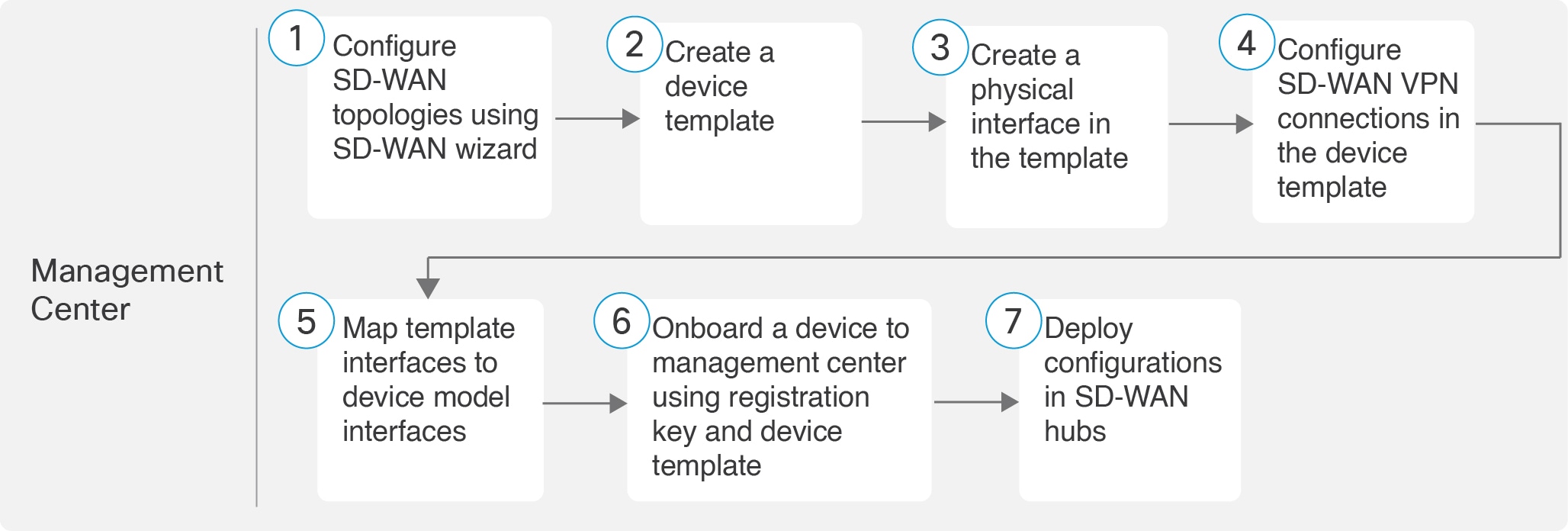
The following flowchart illustrates the workflow for setting up an SD-WAN branch office with dual ISPs using registration key and device templates.

Workflow for Setting Up SD-WAN Branch Office with Dual ISPs Using Registration Key and Device Templates

Step

Task

More Information

Configure SD-WAN topologies using SD-WAN wizard

Configure SD-WAN Topologies Using the SD-WAN Wizard

Create a device template

Create a Device Template

Create a physical interface in the template.

Add a Physical Interface in the Template

Configure SD-WAN VPN connections in the device template.

Configure an SD-WAN VPN Connection in a Device Template

Map template interfaces to device model interfaces.

Map Template Interfaces to Device Model Interfaces

Onboard a device to management center using registration key and device template.

Onboard a Device to Management Center Using a Registration Key and Device Template

Deploy configurations in SD-WAN hubs.

-

Configure SD-WAN Topologies Using the SD-WAN Wizard

The SD-WAN wizard allows you to easily configure VPN tunnels between your centralized headquarters and remote branch sites. Using this wizard, for each spoke, you can use only one WAN interface per SD-WAN topology. However, for dual-ISP setups, you can configure a second SD-WAN topology with the second WAN interface.

In this example, we configure two SD-WAN topologies:

  • SDWAN-VPN1 with outside-isp1 as the spoke's VPN interface for ISP1

  • SDWAN-VPN2 with outside-isp2 as the spoke's VPN interface for ISP2

Before you begin

Ensure that you review Prerequisites for SD-WAN Wizard and Device Templates and Guidelines and Limitations for SD-WAN Wizard and Device Templates.

Procedure


Step 1

Choose Devices > Site To Site, and click Add.

Step 2

In the Topology Name field, enter SDWAN-VPN1 as the name for the SD-WAN VPN topology.

Step 3

Click the SD-WAN Topology radio button and click Create.

Step 4

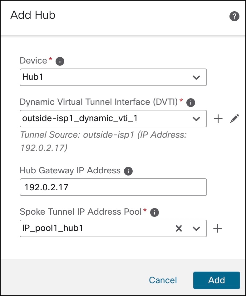
Configure a hub:

  1. Click Add Hub.

  2. From the Device drop-down list, choose a hub.

  3. Click + next to the Dynamic Virtual Tunnel Interface (DVTI) drop-down list to add a dynamic VTI for the hub.

    The Add Virtual Tunnel Interface dialog box is prepopulated with default configurations. However, you must configure the following parameters:

    1. From the Tunnel Source drop-down list, choose the physical interface that is the source of the dynamic VTI. Choose the IP address of this interface from the adjacent drop-down list.

    2. From the Borrow IP drop-down list, choose a loopback interface from the drop-down list. The dynamic VTI inherits this IP address.

      • For SDWAN-VPN1: For Hub1, we use Loopback1 (209.165.201.1) as the Borrow IP.

      • For SDWAN-VPN2: For Hub1, we use Loopback2 (209.165.201.65) as the Borrow IP.

      For more information about the loopback IP addresses of the hubs, see Table 2.

  4. Click OK.

  5. In the Hub Gateway IP Address field, enter the public IP address of the hub's VPN interface or the tunnel source of the dynamic VTI to which the spokes connect.

    This IP address is auto populated if the interface has a static IP address. If hub is behind a NAT device, you must manually configure the post-NAT IP address.

    • For SDWAN-VPN1: For Hub1, the Hub Gateway IP Address is 192.0.2.17.

    • For SDWAN-VPN2: For Hub1, the Hub Gateway IP Address is 192.0.2.33.

    For more information about the IP addresses of the hubs and spokes, see Table 1.

  6. From the Spoke Tunnel IP Address Pool drop-down list, choose an IP address pool or click + to create an address pool.

    Note


    Ensure that you do not check the Allow Overrides check box when you create an address pool in the Add IP Pool dialog box.

    When you add spokes, the wizard auto generates spoke tunnel interfaces, and assigns IP addresses to these spoke interfaces from this IP address pool.

  7. Click Add to save the hub configuration.

    Add Hub dialog box in SD-WAN Wizard
  8. (Optional) To add a secondary hub, repeat Step 4a to Step 4g.

    Hubs in SD-WAN Wizard
  9. Click Next.

Step 5

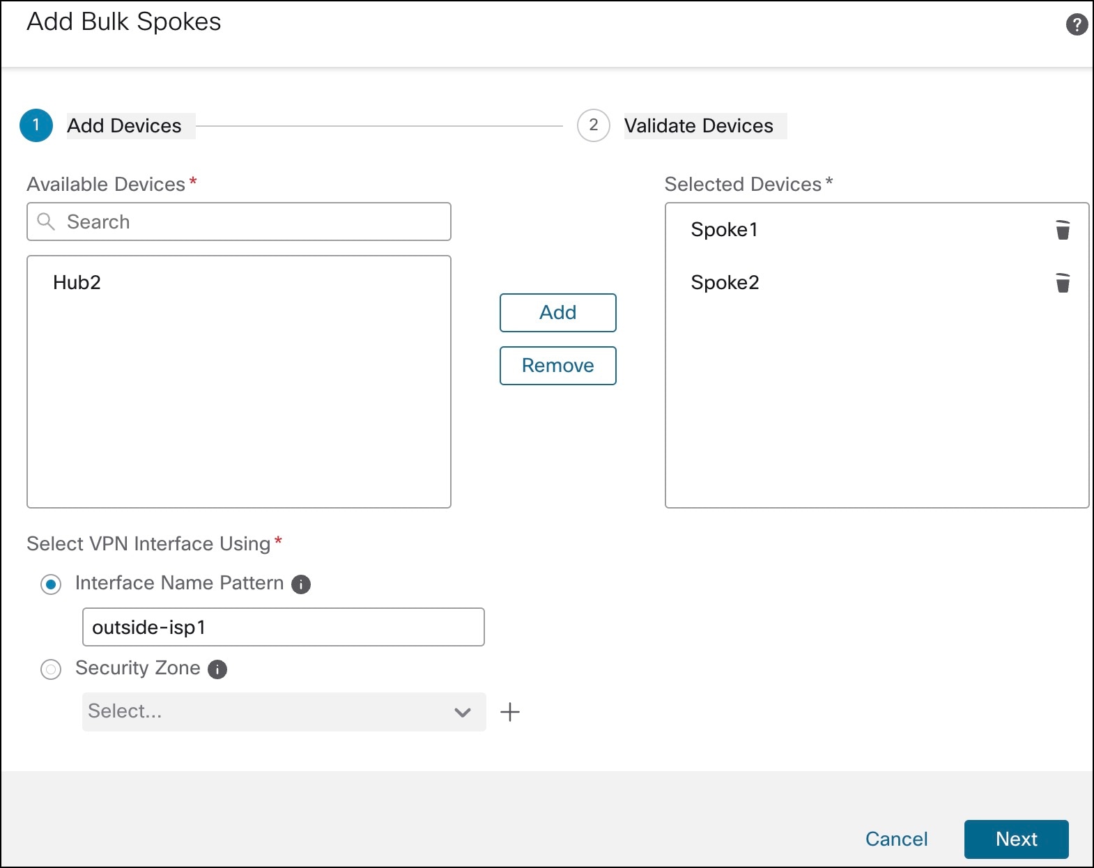
To configure spokes, click Add Spokes (Bulk Addition). In the Add Bulk Spokes dialog box, configure the following parameters:

  1. Choose Spoke1 and Spoke2 from the Available Devices list and click Add to move the devices to Selected Devices.

  2. Use one of the following methods to select the VPN interfaces of the spokes:

    • Click the Interface Name Pattern radio button and specify a string to match the logical name of the internet or WAN interface of the spokes, for example, outside*, wan*. In our example, the string for the ISP1 interface is outside-isp1.

      If the spoke has multiple interfaces with the same pattern, the first interface that matches the pattern is selected for the topology.

    • Click the Security Zone radio button and choose a security zone with the VPN interfaces of the spokes from the drop-down list, or click + to create a security zone.

    Add Bulk Spokes in SD-WAN Wizard
  3. Click Next.

    The wizard validates if the spokes have interfaces with the specified pattern. Only the validated devices are added to the topology.

  4. Click Add.

  5. Click Next.

For each spoke, the wizard automatically selects the hub's DVTI as the tunnel destination IP address.

Note


If the hub’s tunnel source IP address is an IPv6 address, the wizard automatically selects the first IPv6 address of the spokes' selected interface.​ To edit the IPv6 address of a spoke's tunnel source, click the edit icon next to a spoke, choose an IPv6 address from the IP Address drop-down list, and click Save.

Step 6

Configure Authentication Settings for the devices in the SD-WAN topology:

  1. From the Authentication Type drop-down list, choose a manual pre-shared key, an auto-generated pre-shared key, or a certificate for device authentication.

    You can use the default settings in this step and proceed to the next step. If required, you can edit the settings later on. In this example, we use Pre-shared Manual Key for device authentication.

    • Pre-shared Manual Key—Specify the pre-shared key for the VPN connection.

    • Pre-shared Automatic Key—(Default value) The wizard automatically defines the pre-shared key for the VPN connection. Specify the key length in the Pre-shared Key Length field. The range is 1 to 127.

    • Certificate—When you use certificates as the authentication method, the peers obtain digital certificates from a CA server in your PKI infrastructure, and use them to authenticate each other.

  2. Choose one or more algorithms from the Transform Sets drop-down list.

  3. Choose one or more algorithms from the IKEv2 Policies drop-down list.

    Authentication Settings in SD-WAN Wizard
  4. Click Next.

Step 7

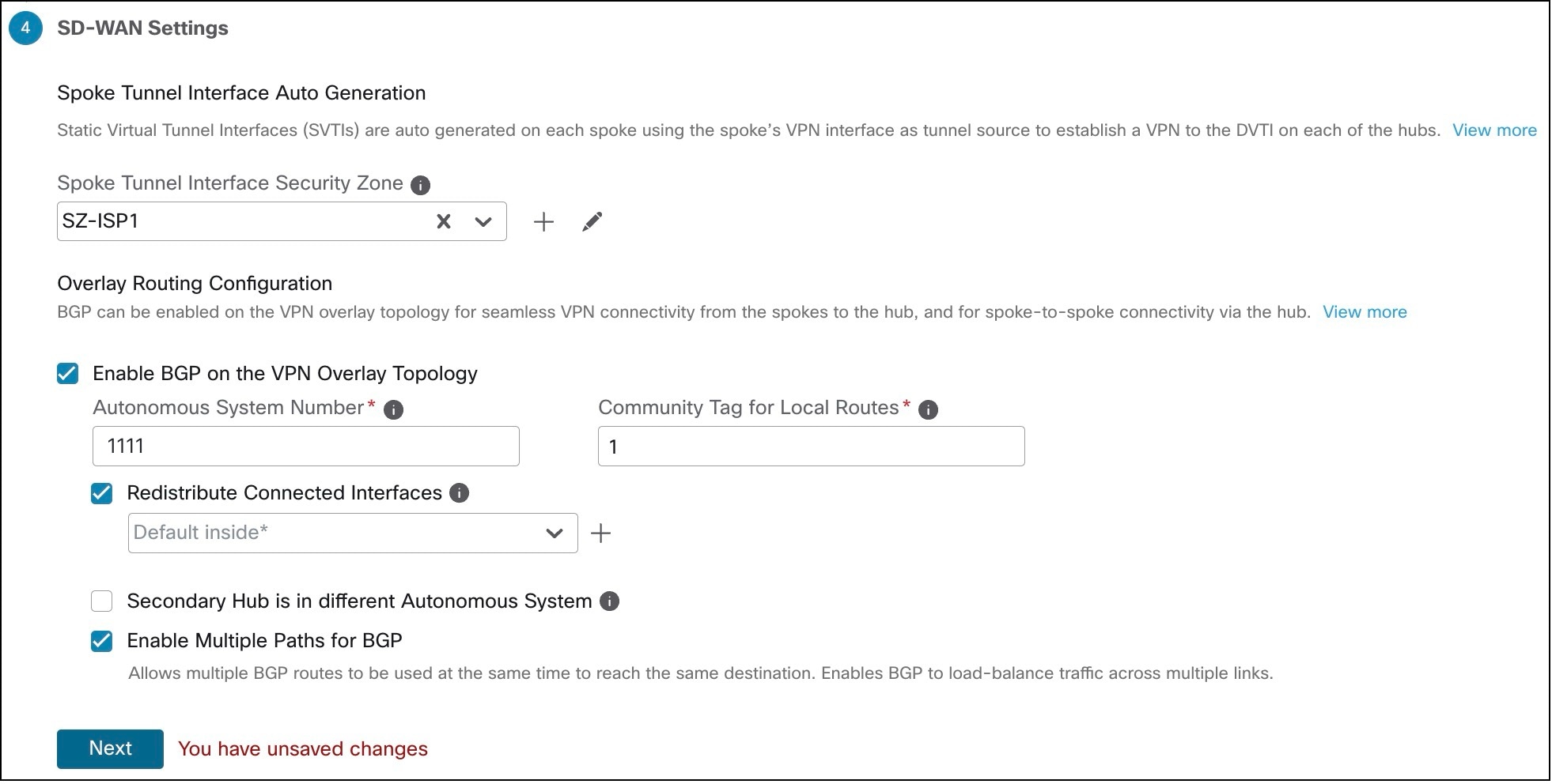
Configure the SD-WAN Settings:

This step involves the auto generation of spoke tunnel interfaces, and BGP configuration of the overlay network.

  1. From the Spoke Tunnel Interface Security Zone drop-down list, choose a security zone or click + to create a security zone to which the wizard automatically adds the spokes' auto-generated Static Virtual Tunnel Interfaces (SVTIs).

  2. Check the Enable BGP on the VPN Overlay Topology check box to automate BGP configurations such as neighbor configurations between the overlay tunnel interfaces and basic route redistribution from the directly connected LAN interfaces of the hubs and spokes.

  3. In the Autonomous System Number field, enter an Autonomous System (AS) number.

    AS number is a unique number for a network with a single routing policy. BGP uses AS numbers to identify networks. The spoke's BGP neighbor configuration is generated based on the corresponding hub’s AS number. Range is from 0 to 65536.

    • If all the hubs and spokes are in the same region, by default, 64512 is the AS number.

    • If the primary and secondary hubs are in different regions, the primary hub and the spokes are configured with 64512 as the AS number, and the secondary hub is configured with a different AS number.

  4. In the Community Tag for Local Routes field, enter the BGP community attribute to tag connected and redistributed local routes. This attribute enables easy route filtering. Note this community string, you must use the same community string for the second SD-WAN VPN topology.

  5. Check the Redistribute Connected Interfaces check box and choose an interface group from the drop-down list or click + to create an interface group with connected inside or LAN interfaces for BGP route redistribution in the overlay topology.

  6. Check the Enable Multiple Paths for BGP check box to allow multiple BGP routes to be used at the same time to reach the same destination. This option enables BGP to load-balance traffic across multiple links.

  7. (Optional) Check the Secondary Hub is in Different Autonomous System check box. This check box appears only if you have a secondary hub in this topology.

  8. In the Autonomous System Number field, enter the AS number for the secondary hub. In our example, both the hubs are in the same region and have the same AS number.

  9. In the Community Tag for Learned Routes field, enter the BGP community attribute to tag routes learned from other SD-WAN peers over the VPN tunnel. This attribute is required only for eBGP configuration when the secondary hub has a different AS number. This field appears only if you have configured two hubs in the SD-WAN topology. In our example, we do not have to configure this value because all the devices are in the same region.

    SD-WAN Settings in SD-WAN Wizard
  10. Click Next.

Step 8

Click Finish to save and validate the SD-WAN topology.

You can view the topology in the Site-to-Site VPN Summary page (Devices > Site-to-site VPN). After you deploy the configurations to all the devices, you can see the status of all the tunnels in this page.


What to do next

  1. Repeat Step 1 to Step 8 to configure the SDWAN-VPN2 topology with the VPN interface for ISP2: outside-isp2.

  2. Configure a point-to-point route-based VPN topology between the two hubs using the route-based VPN wizard to ensure direct communication between these networks.

Create a Device Template

Before you begin

You must be an admin user to create a device template.

Procedure


Step 1

Choose Devices > Template Management.

Step 2

Click Add Device Template.

In the Add Device Template dialog box, configure the following parameters:

  1. In the Name field, enter the name for the template.

  2. (Optional) In the Description field, enter a description for the template.

  3. From the Access Control Policy drop-down list, choose an access control policy.

Add Device Template dialog box

Step 3

Click OK.


Add a Physical Interface in the Template

By default, a device template enables the device to come up with the following physical interfaces:

  • Management interface

  • Inside interface

  • Outside interface

For this dual ISP use case, we need two outside interfaces. To create a physical interface:

Procedure


Step 1

Choose Devices > Template Management.

Step 2

Click the edit icon of the template in which you want to add the physical interface.

Step 3

In the Interfaces tab, click Add Physical Interface.

Step 4

Choose a Slot and Port Index number from the drop-down list.

Step 5

Click Create Interface.

Create physical interface in a device template

You can rename the outside interfaces of the device template. In this example, these interfaces are outside-isp1 and outside-isp2.


Configure an SD-WAN VPN Connection in a Device Template

You must configure an SD-WAN VPN connection to add spokes to SD-WAN topologies using the device template.

Before you begin

Procedure


Step 1

Choose Devices > Template Management.

Step 2

Click the edit icon adjacent to the device template that you want to edit.

Step 3

Click the VPN tab.

Step 4

Click Add VPN Connection.

Step 5

Choose an SD-WAN topology from the VPN Topology drop-down list.

The Add VPN Connection dialog box expands and you can configure the following parameters:

  1. From the VPN Interface drop-down list, choose a WAN-facing or internet-facing physical interface to establish a VPN connection with the hub.

    This list contains all the interfaces configured in the device template. In this example, the VPN interface is outside-isp1.

  2. Use IP Address from the VPN Interface—This drop-down list is auto populated with the IP address variable. For IPv6 address, choose an IPv6 address from the drop-down list.

  3. Check the Local Tunnel (IKE) Identity check box to enable a unique and configurable identity for the VPN tunnel from the spoke to a remote peer.

  4. Identity Type—Key ID is the only supported identity type. Choose a key ID variable from the drop-down list or click + to create a new key ID variable.

  5. Click OK.

    Add VPN Connection in Device Templates

    You can view the VPN connection in the Site-to-Site VPN Connections table.

Step 6

Click Save.

Step 7

Repeat Step 4 to Step 6 to configure another SD-WAN VPN connection using the second outside interface.

In this example, the second outside interface is outside-isp2, and there are two SD-WAN VPN connections:

  • SDWAN-VPN1 with outside-isp1 as the VPN interface

  • SDWAN-VPN2 with outside-isp2 as the VPN interface

Site-to-Site VPN Connections in Device Templates

Map Template Interfaces to Device Model Interfaces

For each model, you can specify which template interface corresponds to which model interface. You can map a template to one or more models as long as the interface configurations are valid for all the mapped models. For example, if the template includes switch ports and VLAN interfaces, then that template can only be applied to a Firepower 1010.

Procedure


Step 1

Choose Devices > Template Management.

Step 2

Click Add Model Mapping for the template in which you want to create the model mapping. Alternatively, you can click the edit icon of the template and choose Template Settings > Model Mapping.

Step 3

Click Add Model Mapping

Step 4

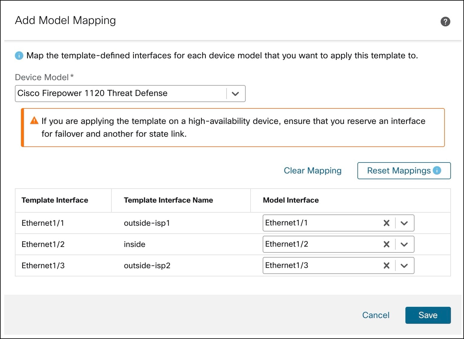
Choose the Device Model from the drop-down list.

In this example, we choose a Cisco Firepower 1120 Threat Defense device.

Step 5

Map the template interfaces to the device model interfaces by choosing the interface from the Model Interface drop-down list.

Note


Click Clear Mapping to remove defined model mapping. Click Reset Mappings for default interface mapping in which the mapping is done based on the slot and port index order of the interface names.

Step 6

Click Save.

Note


Some configurations in the template may not be supported on all device models. Unsupported configurations, if any, are not applied to the device. The Device Template Apply Report provides details about such configurations.

Add Model Mapping in Device Template

Onboard a Device to Management Center Using a Registration Key and Device Template

You can use the device template to add a device, register the device with Management Center, and bring up the device with the given template configurations.

We recommend that you create a checklist to ensure that all the configurations in the template have been entered correctly before applying the template on the device.

The following is a sample checklist:

  • Check version, model, operation modes.

  • Check list of variables and overrides.

  • Check sanity of variable and override values.

  • Check if the required model mappings exist.

  • Check if parallel device template operations are in progress.


Note


If you add a Threat Defense device that will be managed by a data interface for Management Center connectivity, ensure that you configure the template to be compatible with the connectivity parameters of the device. For more information, see Configure a Template for Threat Defense Devices Managed Through the Data Interface.


Procedure


Step 1

Choose Devices > Device Management.

Step 2

Click Add > Device (Wizard).

Step 3

In the Add Device (Wizard) window, choose Registration Key to register a device using registration key.

Step 1 of Add Device Wizard

Step 4

Click Next.

Step 5

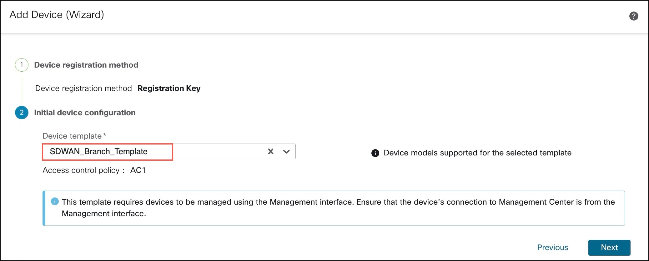
Choose a template from the Device template drop-down list.

Step 2 of Add Device Wizard

Step 6

Click Next.

Step 7

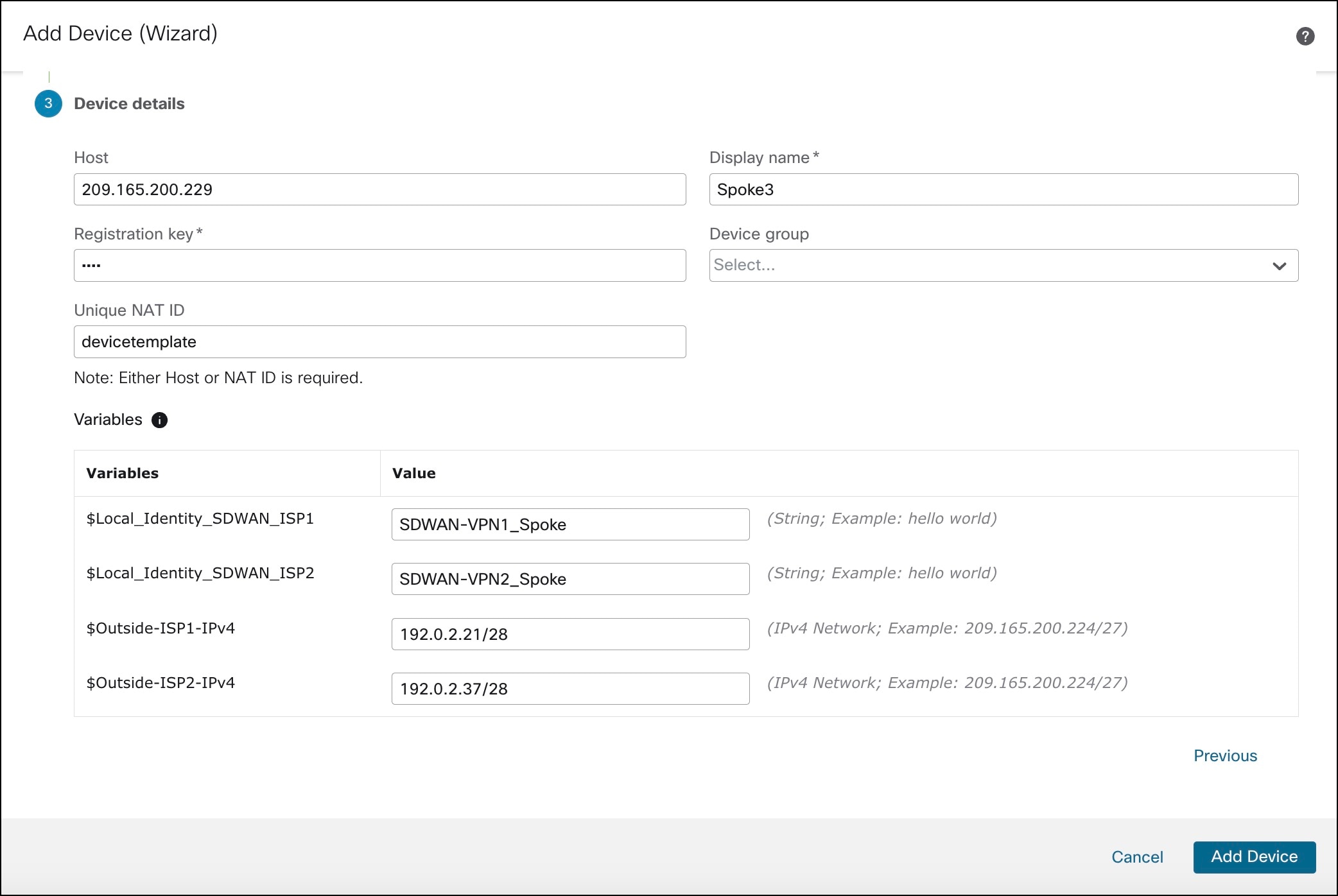
In the Host field, enter the IP address or the hostname of the device you want to add.

The hostname of the device is the fully qualified domain name or the name that resolves through the local DNS to a valid IP address. Use a hostname rather than an IP address if your network uses DHCP to assign IP addresses.

Step 8

In the Display name field, enter a name for the device as you want it to display in the management center.

Step 9

In the Registration key field, enter the same registration key that you used when you configured the device to be managed by the management center. The registration key is a one-time-use shared secret. The key can include alphanumeric characters and hyphens (-).

Step 10

(Optional) From the Device group drop-down list, choose a device group in which the device is added.

Step 11

Enter values for the Variables and Network object overrides.

Step 3 of Add Device Wizard

Step 12

Click Add Device to initiate device registration.

The template configurations are applied after the device is successfully registered with the Management Center.

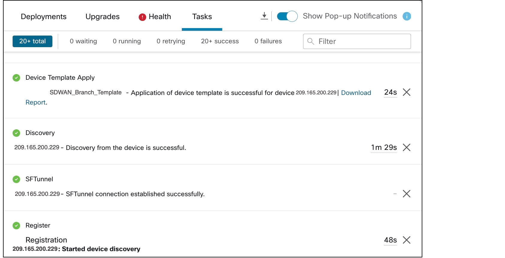
In the Notifications > Tasks window, you can view the messages related to the device registration, device discovery, and device template application.

Notifications about device registration and template application on a device

A Device Template Apply report is generated after the apply template task is completed. This report is generated on both successful and unsuccessful application of the template on the device. You will see a link to this report in the Notifications > Tasks window.


Verify Tunnel Statuses and Configurations of SD-WAN Topologies

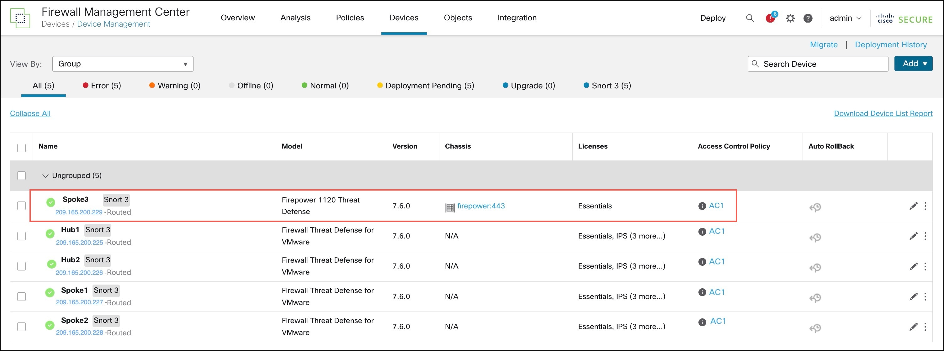
View the Onboarded Device in the Device Management Page

After the device template is successfully applied on the device, you can view the device in the Device Management page.

Onboarded device in Device Management page

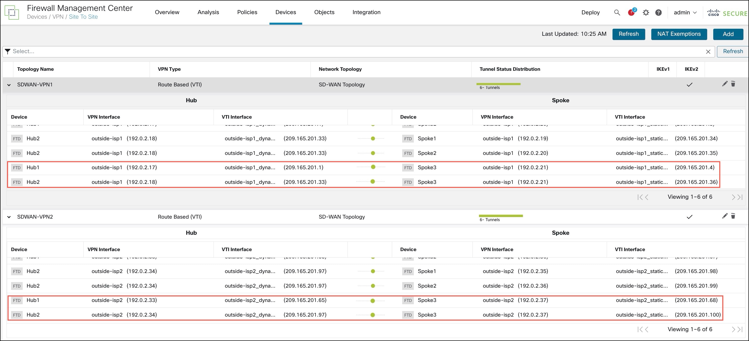
Verify Tunnel Statuses in the Site-to-Site VPN Summary Page

To verify the statuses of the VPN tunnels, choose Device > VPN > Site To Site.

After the device template is successfully applied on the device, the device (Spoke3) gets added to the SD-WAN topologies.You can view the VPN tunnels between the hubs and the spokes, and also the VPN tunnels between the hubs and the onboarded device, Spoke3.

Tunnel Statuses in the Site-to-Site VPN Summary Page

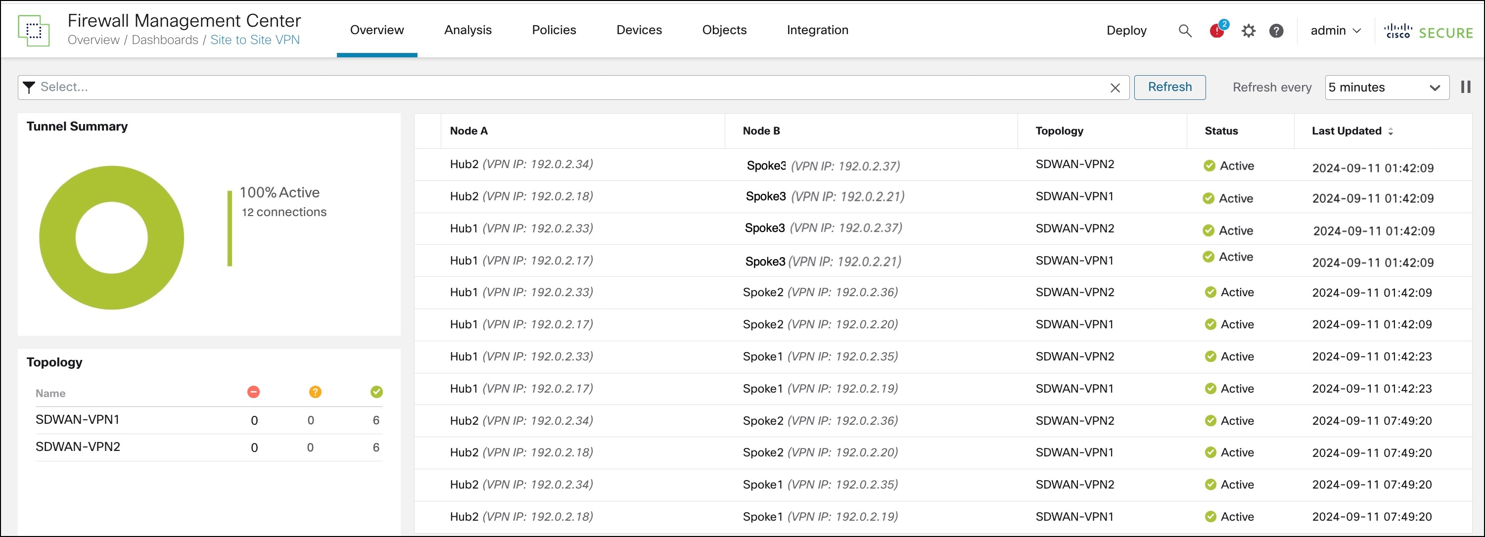
Verify Tunnel Statuses in the Site-to-Site VPN Dashboard

To view details of the SD-WAN VPN tunnels, choose Overview > Dashboards > Site-to-site VPN.

Following are the VPN tunnels of the two SD-WAN topologies: SDWAN-VPN1 and SDWAN-VPN2:

Tunnel Statuses in the Site-to-Site VPN Dashboard

You can also see the VPN tunnels between Spoke3 and the two hubs.

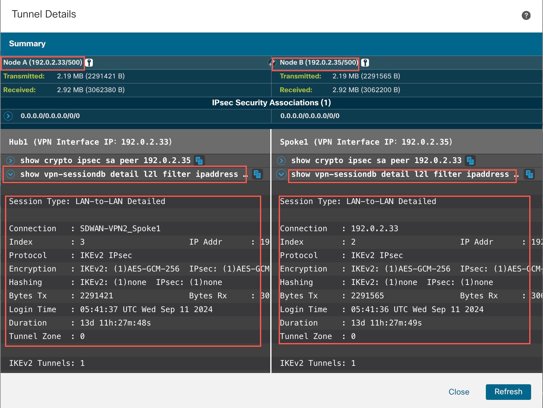
To see more details about each tunnel:

  1. For each tunnel, hover your cursor over a topology and click the View icon to view more information about the tunnels.
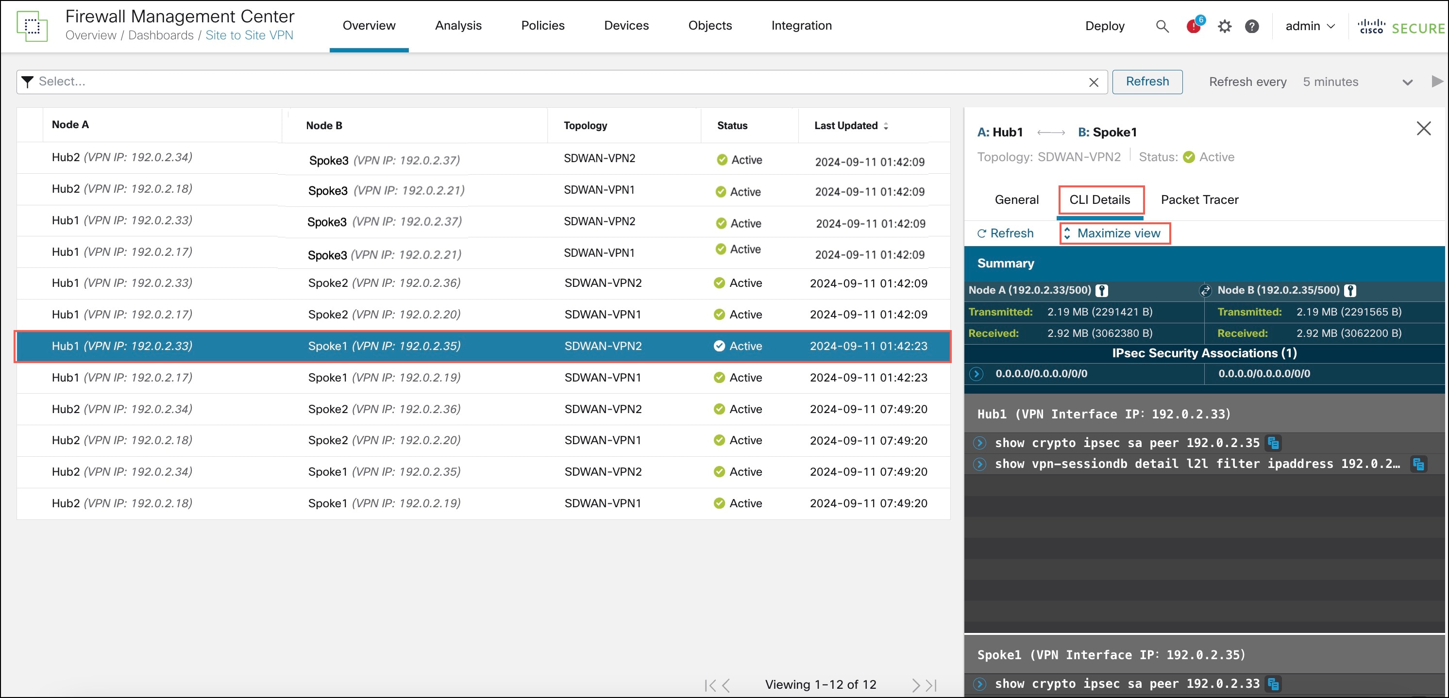
  2. Click the CLI Details tab.

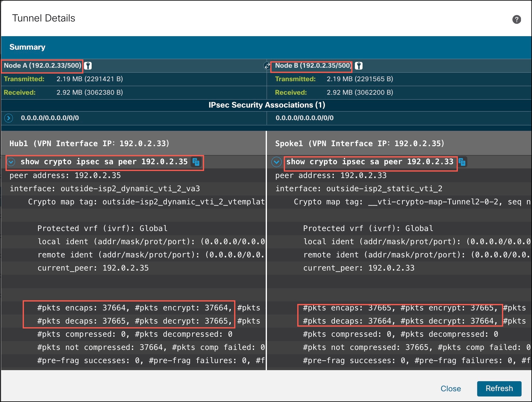
  3. Click Maximize View. You can view the output of the following commands:

    • show crypto ipsec sa peer: Shows the number of packets that are transmitted through the tunnel.

      Output of show crypto sa peer command of Hub1
    • show vpn-sessiondb detail l2l filter ipaddress: Shows more detailed data for the VPN connection.

      Output of show vpn-sessiondb detail l2lfilter ipaddress command of Hub1

Verify Routing Information of the Threat Defense Device

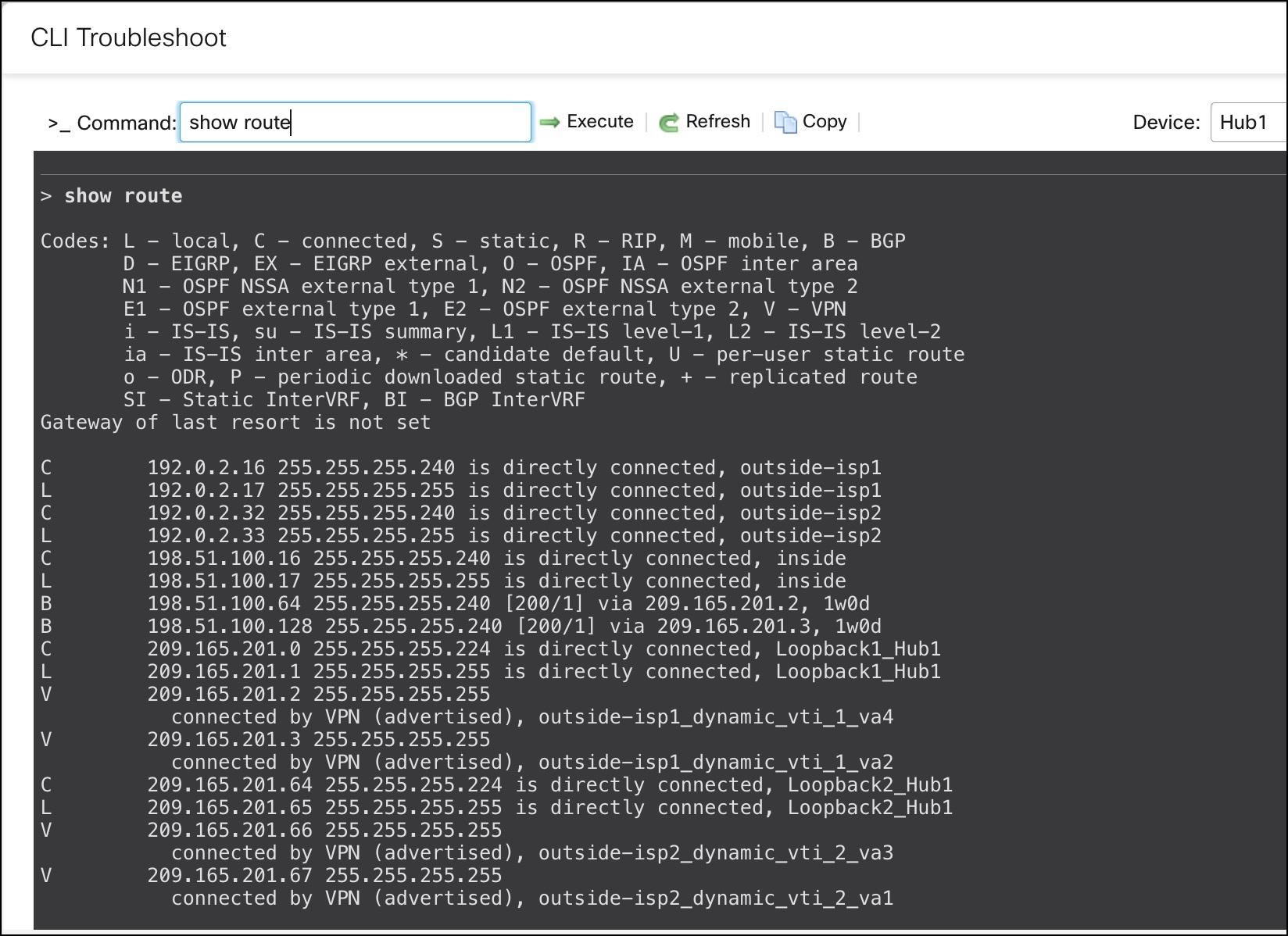
To verify the routing information of the hub and the spokes, use the show route command on the device using the Management Center or the device CLI. You can also use the show bgp command.

  1. In the Management Center, choose Devices > Device Management.

  2. Click the edit icon adjacent to the device.

  3. Click the Device tab.

  4. Click CLI in the General card.

    In the CLI Troubleshoot window, enter show route in the Command field and click Execute.

    show route command for Hub1

    You can also use the show bgp or show bgp summary commands.

View Tunnel Interface Configurations of the Threat Defense Device

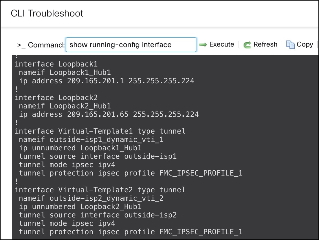
To verify the interface configuration on the Threat Defense device, use the show running-config interface command.

Output of show running-config interface

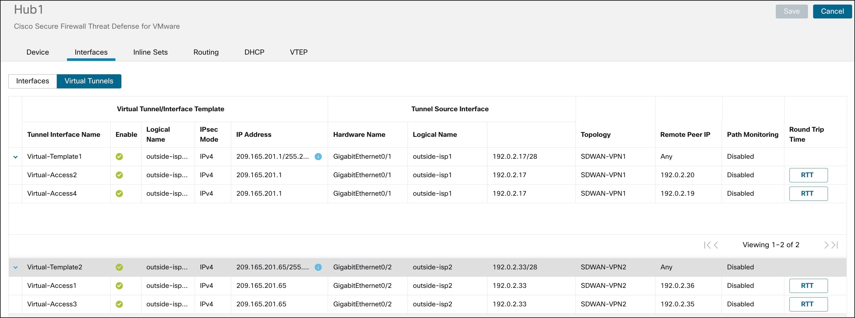
To view the dynamic VTIs of hubs and static VTIs of spokes:

  1. Choose Devices > Device Management.

  2. Click the edit icon adjacent to the device.

  3. Click the Interfaces tab.

  4. Click the Virtual Tunnels tab.

    For each VTI, you can view details such as name, IP address, IPsec mode, tunnel source interface details, topology, and remote peer IP.

    The dynamic VTI and the dynamically created virtual access interfaces of Hub1 are shown in the figure below:

    Dynamic VTI and the dynamically created virtual access interfaces of Hub1

    The static VTIs created on Spoke1 are shown in the figure below:

Troubleshoot Device Templates and SD-WAN Topologies

Troubleshoot Device Templates

  • Use the Device Template Apply report for initial troubleshooting:

    1. Check the errors mentioned in the report.

    2. Review variable values and network object overrides values. Check for overlaps and incompatibilities.

    3. Check model mappings to ensure if the correct model mappings exist. Delete or add mappings accordingly.

    4. Verify if the device or template is locked because of tasks such as application or modification of the template.

    5. See the Management Center audit logs to find any other issues and resolve them.

  • Use Audit Logs:

    Logs related to application of the device template, configuration updates, device template creation, and deletion, are logged under audit logs. The device template audit logs are added to the log both at the start and at the end of the task to apply the template on the device.

    An audit diff file is also generated that enables you to view configuration changes that have been done during application of the template on the device. To view the diff file:

    1. Choose System > Monitoring > Audit.

      The device template logs are logged under the subsystem Devices > Template Management.

    2. Click the diff icon to open a new window that displays the configuration changes that have been done during the application of the template on the device.

Troubleshoot SD-WAN Topologies

After the deployment, use the following CLI commands and tools to debug issues related to route-based VPN tunnels on Threat Defense devices.

CLI and Debug Commands

Command

Description

ping

Ping the outside IP address of the peer to the check the connectivity between the devices.

show vpnsession db

Displays summary information about current VPN sessions.

debug crypto condition peer <peer-IP>

Enable conditional debugging for a particular peer

debug vti 255

Debug the Virtual Tunnel Interface information.

Packet Tracer

The Packet Tracer tool allows you to test policy configurations by modeling a packet with source and destination addresses, and protocol characteristics. Besides verifying your configuration, you can use this tool to debug unexpected behaviour, such as packets being denied access.

To use a packet tracer on Threat Defense devices, choose Devices > Packet Tracer. You must be an Admin or Maintenance user to use this tool.

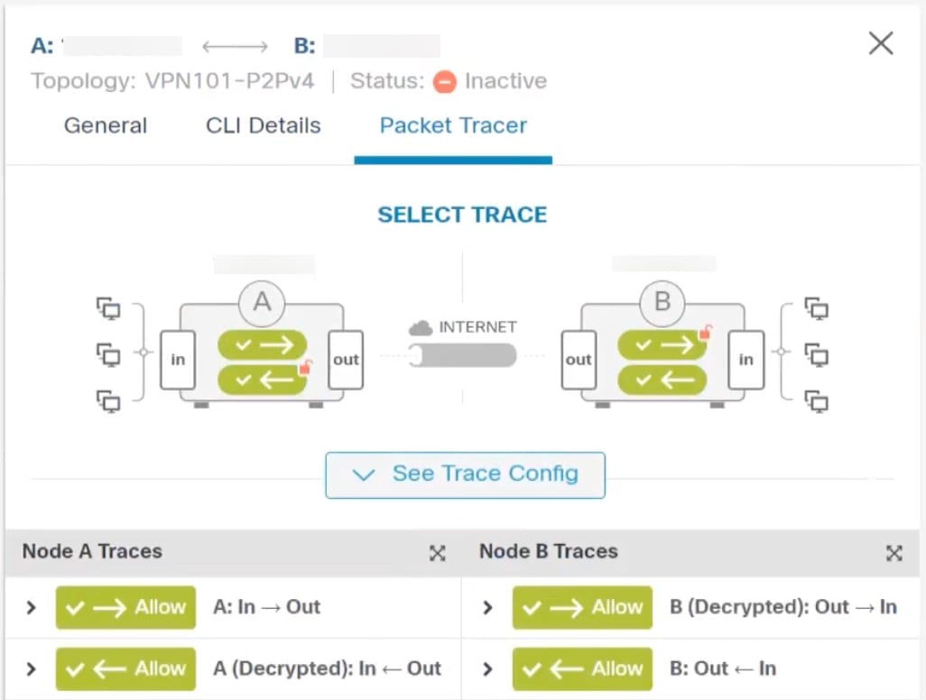
You can also use the Packet Tracer in the Site to Site VPN Dashboard to troubleshoot VPN tunnels between two Threat Defense devices.

  1. Choose Overview > Dashboards.

  2. For each tunnel, hover your cursor over a topology and click the View icon to view more information about the tunnels.
  3. Click the Packet Tracer tab.

  4. Configure the parameters.

  5. Click Trace Now.

  6. After the trace completes, you can view the output of the trace with the results of each module.